|
1
|
INSPECT LF CONTROL UNIT CONNECTOR CONDITION
• Switch the ignition to off.
• Disconnect the negative battery cable.
• Disconnect the LF control unit connector.
• Inspect the connector engagement and connection condition and inspect the terminals for damage, deformation, corrosion, or disconnection.
• Is the connector normal?
|
Yes
|
Go to the next step.
|
|
No
|
Repair or replace the connector, then go to Step 6.
|
|
2
|
INSPECT START STOP UNIT CONNECTOR CONDITION
• Disconnect the start stop unit connector.
• Inspect the connector engagement and connection condition and inspect the terminals for damage, deformation, corrosion, or disconnection.
• Is the connector normal?
|
Yes
|
Go to the next step.
|
|
No
|
Repair or replace the connector, then go to Step 6.
|
|
3
|
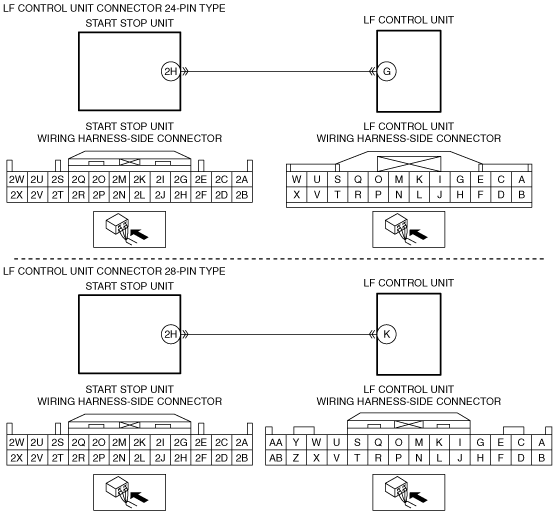
INSPECT LF CONTROL UNIT CIRCUIT FOR SHORT TO GROUND
• Verify that the start stop unit and LF control unit connectors are disconnected.
• Inspect for continuity between LF control unit terminal G (24-pin type)/K (28-pin type) (vehicle wiring harness side) and body ground.
• Is there continuity?
|
Yes
|
Repair or replace the wiring harness which is shorted to ground, then go to Step 6.
|
|
No
|
Go to the next step.
|
|
4
|
INSPECT LF CONTROL UNIT CIRCUIT FOR OPEN CIRCUIT
• Verify that the start stop unit and LF control unit connectors are disconnected.
• Inspect the wiring harness for continuity between start stop unit terminal 2H (vehicle wiring harness side) and LF control unit terminal G (24-pin type)/K (28-pin type) (vehicle wiring harness side).
• Is there continuity?
|
Yes
|
Go to the next step.
|
|
No
|
Repair or replace the wiring harness which has an open circuit, then go to Step 6.
|
|
5
|
INSPECT LF CONTROL UNIT
• Inspect the LF control unit.
• Is the LF control unit normal?
|
Yes
|
Go to the next step.
|
|
No
|
Replace the LF control unit, then go to the next step.
|
|
6
|
VERIFY THAT REPAIRS HAVE BEEN COMPLETED
• Reconnect all the disconnected connectors.
• Reconnect the disconnected negative battery cable.
• Clear DTCs for the advanced keyless entry system using the M-MDS.
• Switch the ignition ON (engine off or on) and wait for 5 s or more.
• Perform the advanced keyless entry system DTC inspection using the M-MDS.
• Is DTC B13C3:09 displayed?
|
Yes
|
Repeat the inspection from Step 1.
• If the malfunction recurs, replace the start stop unit, then go to the next step.
|
|
No
|
Go to the next step.
|
|
7
|
VERIFY IF OTHER DTCs DISPLAYED
• Are any other DTCs displayed?
|
Yes
|
Repair the malfunctioning part according to the applicable DTC troubleshooting.
|
|
No
|
DTC troubleshooting completed.
|