ac5wzn00001854
|
SEAT WARMER SYSTEM
id091300101200
Purpose
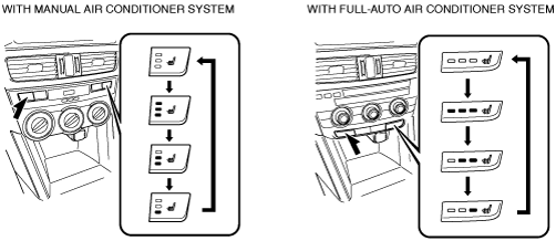
Function
ac5wzn00001854
|
|
Switch display |
Temperature level |
Average temperature around seat warmer unit |
||
|---|---|---|---|---|
|
With manual air conditioner system |
With full-auto air conditioner system |
Seat cushion side |
Seat back side |
|
 |
 |
0
|
—
|
|
 |
 |
1
|
Approx. 37°C {67 F}
|
|
 |
 |
2
|
Approx. 40°C {72 F}
|
Approx. 42°C {75 F}
|
 |
 |
3
|
Approx. 42°C {75 F}
|
Approx. 47°C {85 F}
|
|
Temperature level
|
Average temperature around seat warmer unit (seat cushion side)
|
|||
|
Rag type
|
Leather type
|
|||
|
Increase start temperature
|
Decrease start temperature
|
Increase start temperature
|
Decrease start temperature
|
|
|
0
|
—
|
|||
|
1
|
Approx. 23°C {42 F}
|
Approx. 25°C {45 F}
|
Approx. 23°C {42 F}
|
Approx. 25°C {45 F}
|
|
2
|
Approx. 23°C {58 F}
|
Approx. 34°C {61 F}
|
Approx. 30°C {54 F}
|
Approx. 32°C {58 F}
|
|
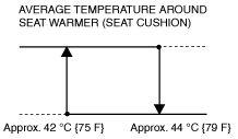
3
|
Approx. 42°C {75 F}
|
Approx. 44°C {79 F}
|
Approx. 38°C {68 F}
|
Approx. 40°C {72 F}
|
Ex.) Cloth-type temperature level is 3:
ac5wzn00002375
|
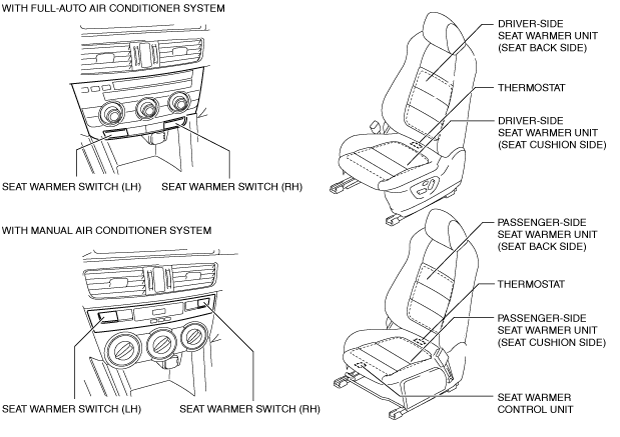
Structural view
ac5wzn00001524
|
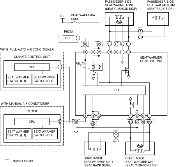
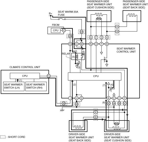
System wiring diagram
ac5uuw00004882
|
Operation
Ex.) Seat warmer temperature level on cloth-type driver's side is set at 3 (with full-auto air conditioner system):
1. The climate control unit determines (1) the average increase temperature of the seat warmer unit by operating the seat warmer switch (driver-side).
2. The climate control unit sends (2) the temperature level "3" signal for the seat warmer unit to the CPU of the seat warmer control unit.
3. When the CPU of the seat warmer control unit receives the operation level "3" signal from the climate control unit, it supplies the base current to the transistor built into the seat warmer control unit (3), and the gate voltage is applied to the FET simultaneously (4).
4. If the base current is supplied, the transistor supplies collector current to the relay coil (5).
5. If collector current is supplied, the relay coil energizes and turns on the relay switch (6).
6. When the gate voltage is applied, the FET completes the circuit between seat warmer control unit terminal A and ground (7).
7. When the relay switch built into the seat warmer control unit turns on and the FET circuit is completed, the driver-side seat warmer unit circuit is completed (8) and the driver-side front seat cushion and front seat back warm.
ac5uun00002144
|
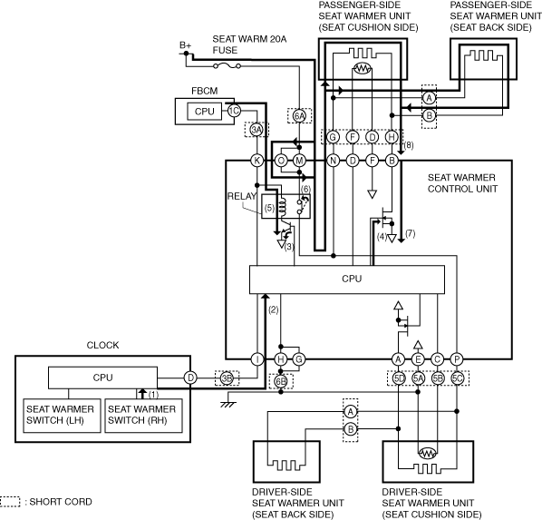
Ex.) Seat warmer temperature level on cloth-type passenger-side is set at 3 (with manual air conditioner system):
1. The climate control unit determines (1) the average increase temperature of the seat warmer unit by operating the seat warmer switch (passenger-side).
2. The climate control unit sends (2) the temperature level "3" signal for the seat warmer unit to the CPU of the seat warmer control unit.
3. When the CPU of the seat warmer control unit receives the operation level "3" signal from the climate control unit, it supplies the base current to the transistor built into the seat warmer control unit (3), and the gate voltage is applied to the FET simultaneously (4).
4. If the base current is supplied, the transistor supplies collector current to the relay coil (5).
5. If collector current is supplied, the relay coil energizes and turns on the relay switch (6).
6. When the gate voltage is applied, the FET completes the circuit between seat warmer control unit terminal B and ground (7).
7. When the relay switch built into the seat warmer control unit turns on and the FET circuit is completed, the driver-side seat warmer unit circuit is completed (8) and the driver-side front seat cushion and front seat back warms.
ac5uun00002145
|
Fail-safe