ac5uun00001109
|
ON-BOARD DIAGNOSIS SYSTEM [ADVANCED KEYLESS ENTRY SYSTEM]
id091400111233
Outline
Outline
Malfunction detection function
|
DTC No. |
KEY warning light (red) |
Description |
Fail-safe function |
Drive cycle |
Self test type*1 |
Memory function |
|---|---|---|---|---|---|---|
|
B10C6:1F
|
On
|
Keyless antenna (exterior, rear) circuit malfunction
|
×
|
—
|
C, D
|
×
|
|
B10C7:1F
|
On
|
Keyless antenna (interior, rear) circuit malfunction
|
×
|
—
|
C, D
|
×
|
|
B10C9:1F
|
On
|
Keyless antenna (interior, front) circuit malfunction
|
×
|
—
|
C, D
|
×
|
|
B10D1:23
|
On
|
Request switch (LF) circuit malfunction
|
—
|
—
|
C
|
×
|
|
B10D3:23
|
On
|
Request switch (RF) circuit malfunction
|
—
|
—
|
C
|
×
|
|
B11C4:23
|
On
|
Request switch (liftgate) circuit malfunction
|
—
|
—
|
C
|
×
|
|
B11FD:1F
|
On
|
Keyless antenna (exterior, LF) circuit malfunction
|
×
|
—
|
C, D
|
×
|
|
B1210:1F
|
On
|
Keyless antenna (exterior, RF) circuit malfunction
|
×
|
—
|
C, D
|
×
|
|
B13C3:04
|
On
|
LF control unit internal malfunction
|
×
|
—
|
C
|
×
|
|
B13C3:09
|
On
|
LF control unit malfunction
|
×
|
—
|
C
|
×
|
|
B13C3:16
|
On
|
LF control unit power supply voltage decrease input
|
×
|
—
|
C
|
×
|
|
B13C3:29
|
On
|
Communication error with LF control unit
|
×
|
—
|
C
|
×
|
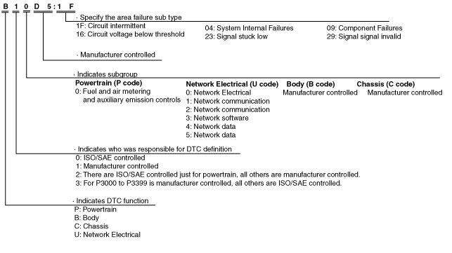
DTC 7-digit code definition
ac5uun00001109
|
Status byte for DTC
ac5wzn00002015
|
Detection condition for the applicable DTC
|
DTC |
System malfunction location |
Detection condition |
|---|---|---|
|
B10C6:1F
|
Keyless antenna (exterior, rear) circuit malfunction
|
The start stop unit detects an open circuit in the keyless antenna (exterior, rear) or a short to ground with the ignition switched off.
|
|
B10C7:1F
|
Keyless antenna (interior, rear) circuit malfunction
|
The start stop unit detects an open circuit in the keyless antenna (interior, rear) or a short to ground with the ignition switched off.
|
|
B10C9:1F
|
Keyless antenna (interior, front) circuit malfunction
|
The start stop unit detects an open circuit in the keyless antenna (interior, front) or a short to ground with the ignition switched off.
|
|
B10D1:23
|
Request switch (LF) circuit malfunction
|
With the ignition switched ON (engine on), the start stop unit detects that the vehicle speed is 5 km/h {3 mph} or more for a continuous 2 min or more and the request switch (LF) is on 7 times or more until the vehicle speed is less than 5 km/h {3 mph}.
|
|
B10D3:23
|
Request switch (RF) circuit malfunction
|
With the ignition switched ON (engine on), the start stop unit detects that the vehicle speed is 5 km/h {3 mph} or more for a continuous 2 min or more and the request switch (RF) is on 7 times or more until the vehicle speed is less than 5 km/h {3 mph}.
|
|
B11C4:23
|
Request switch (liftgate) circuit malfunction
|
With the ignition switched ON (engine on), the start stop unit detects that the vehicle speed is 5 km/h {3 mph} or more for a continuous 2 min or more and the request switch (liftgate) is on 7 times or more until the vehicle speed is less than 5 km/h {3 mph}.
|
|
B11FD:1F
|
Keyless antenna (exterior, LF) malfunction
|
The start stop unit detects an open circuit in the keyless antenna (exterior, LF) or a short to ground with the ignition switched off.
|
|
B1210:1F
|
Keyless antenna (exterior, RF) malfunction
|
The start stop unit detects an open circuit in the keyless antenna (exterior, RF) or a short to ground with the ignition switched off.
|
|
B13C3:04
|
LF control unit internal malfunction
|
LF control unit internal malfunction detected
|
|
B13C3:09
|
LF control unit malfunction
|
• The start stop unit detects that the LF State signal of the LF control unit is low for 5 s or more.
• With the communication between the start stop unit and LF control unit being performed normally, there is no response from the LF control unit even though there is a signal transmission request from the start stop unit to the LF control unit, and the LF state signal becomes low.
|
|
B13C3:16
|
LF control unit power supply voltage decrease input
|
With the ignition switched ON (engine off), start stop unit power supply circuit (+B1) voltage of 8.5 V or more or less than 16.5 V and LF control unit power supply circuit voltage of 5 V or more or less than 8.5 V are detected for 5 s or more.
|
|
B13C3:29
|
Communication error with LF control unit
|
The start stop unit detects communication error with LF control unit 10 times in a series.
|
Data monitor function
|
PID |
Unit/Operation |
Data contents |
Inspection item(s) |
|---|---|---|---|
|
LG/T_LK_SW
|
Off/On
|
• Off: Request switch (liftgate) is off.
• On: Request switch (liftgate) is on.
|
Request switch (liftgate)
|
|
RQ_SW_LF
|
Off/On
|
• Off: Request switch (LF) is off.
• On: Request switch (LF) is on.
|
Request switch (LF)
|
|
RQ_SW_RF
|
Off/On
|
• Off: Request switch (RF) is off.
• On: Request switch (RF) is on.
|
Request switch (RF)
|