• If there are any non-illuminated area, replace the instrument cluster.
ac5wzw00003785
|
INSTRUMENT CLUSTER INSPECTION
id092200010600
Speedometer inspection
Using a speedometer tester
1. Adjust the tire pressure to the specification.
2. Using a speedometer tester, verify that the tester reading is as indicated in the following table.
European (L.H.D. U.K.), General (L.H.D. R.H.D.) specs., Australian specs.
|
Speedometer tester indication (km/h) |
Allowable range (km/h) |
|---|---|
|
20
|
20—25
|
|
40
|
40—45
|
|
60
|
61—66
|
|
80
|
81—86
|
|
100
|
102—107
|
|
120
|
122—129
|
|
140
|
142—150
|
|
160
|
163—170
|
|
180
|
183—181
|
|
200
|
204—211
|
|
220
|
224—232
|
|
240
|
244—253
|
U.K. specs.
|
Speedometer tester indication (mph) |
Allowable range (mph) |
|---|---|
|
10
|
10—13
|
|
20
|
20—23
|
|
30
|
30—33
|
|
40
|
40—43
|
|
50
|
51—54
|
|
60
|
61—64
|
|
70
|
71—75
|
|
80
|
81—86
|
|
90
|
91—96
|
|
100
|
102—106
|
|
110
|
112—116
|
|
120
|
122—127
|
|
130
|
132—137
|
|
140
|
142—148
|
|
150
|
153—158
|
General (L.H.D. R.H.D.) specs.,
|
Speedometer tester indication (km/h) |
Allowable range (km/h) |
|---|---|
|
20
|
18—22
|
|
40
|
38—42
|
|
60
|
58—62
|
|
80
|
78—82
|
|
100
|
98—102
|
|
120
|
117—123
|
|
140
|
137—143
|
|
160
|
157—163
|
|
180
|
177—183
|
|
200
|
197—203
|
|
220
|
216—224
|
|
240
|
236—244
|
3. Verify that the speedometer reading is within the range indicated in the table.
Using the M-MDS
1. Connect the M-MDS to the DLC-2.
2. After vehicle identification, select the following from the M-MDS initialization screen.
3. Using “SPDMTR”, verify that the displayed information is as indicated in the table.
European (L.H.D. U.K.), General (L.H.D. R.H.D.) specs., Australian specs.
|
M-MDS display
|
Instrument cluster display
|
|
60 km/h
|
Speedometer needle moves to approx. 61—66 km/h {38—41 mph}.
|
|
120 km/h
|
Speedometer needle moves to approx. 122—129 km/h {75.9—80.1 mph}.
|
|
Off
|
Speedometer needle moves to the bottommost position.
|
General (L.H.D. R.H.D.) specs.,
|
M-MDS display
|
Instrument cluster display
|
|
60 km/h
|
Speedometer needle moves to approx. 58—62 km/h {36—39 mph}.
|
|
120 km/h
|
Speedometer needle moves to approx. 117—123 km/h {72.8—76.4 mph}.
|
|
Off
|
Speedometer needle moves to the bottommost position.
|
Tachometer inspection
1. Connect the M-MDS to the DLC-2.
2. After vehicle identification, select the following from the M-MDS initialization screen.
3. Using “TACHOMTR”, verify that the displayed information is as indicated in the table.
|
M-MDS display
|
Instrument cluster display
|
|
3000 RPM
|
Tachometer needle moves to approx. 3,050 rpm.
|
|
6000 RPM
|
Tachometer needle moves to approx. 6,100 rpm.
|
|
Off
|
Tachometer needle moves to bottommost position.
|
LCD Inspection
Without TFT LCD display
1. Connect the M-MDS to the DLC-2.
2. After vehicle identification, select the following from the M-MDS initialization screen.
3. Using “LCD_SEG”, verify that the LCD is illuminated.
ac5wzw00003785
|
With TFT LCD display
1. Connect the M-MDS to the DLC-2.
2. After vehicle identification, select the following from the M-MDS initialization screen.
3. Using “LCD_SEG”, verify that the LCD is illuminated.
ac5wzw00002911
|
Warning/Indicator Light Illumination Inspection
1. Connect the M-MDS to the DLC-2.
2. After vehicle identification, select the following from the M-MDS initialization screen.
3. Using “WL+IL”, verify that the warning/indicator lights in the following table are illuminated.
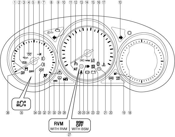
Without TFT LCD display
ac5jjn00000646
|
|
No. |
Warning/Indicator lights |
Name |
Comment |
|---|---|---|---|
|
1
|
 |
TCS/DSC indicator light
|
—
|
|
2
|
 |
High beam control (HBC) system indicator light (green)/high beam control system (HBC) warning light (amber)
|
With HBC System
|
|
3
|
 |
Engine oil warning light
|
—
|
|
4
|
 |
Glow indicator light
|
SKYACTIV-D 2.2
|
|
5
|
 |
Diesel particulate filter indicator light
|
SKYACTIV-D 2.2
|
|
6
|
 |
KEY warning light (red)/indicator light (green)
|
—
|
|
7
|
 |
Front fog light indicator light
|
With front fog light
|
|
8
|
 |
Wrench indicator light
|
SKYACTIV-D 2.2
|
|
9
|
 |
Check engine light
|
—
|
|
10
|
 |
Turn signal/hazard warning indicator lights
|
—
|
|
11
|
 |
Automatic transaxle warning light
|
ATX
|
|
12
|
 |
Cruise main indicator light (amber)/cruise set indicator light (green)
|
With cruise control system
|
|
13
|
 |
Lights-on indicator light
|
—
|
|
14
|
 |
i-stop warning light (amber)/indicator light (green)
|
With i-stop system
|
|
15
|
 |
Lane departure warning system (LDWS) indicator light (green)/lane departure warning system (LDWS) warning light (amber)
|
With LDWS
|
|
16
|
 |
Door-ajar warning light
|
—
|
|
17
|
 |
High engine coolant temperature warning light (red)/low engine coolant temperature indicator light (blue)
|
—
|
|
18
|
 |
Low fuel warning light
|
—
|
|
19
|
 |
120 km/h warning light
|
With 120 km/h warning light
|
|
20
|
 |
ABS warning light
|
—
|
|
21
|
 |
Low washer fluid level warning light
|
With washer fluid-level sensor
|
|
22
|
 |
AFS OFF indicator light
|
With AFS
|
|
23
|
 |
Charging system warning light
|
—
|
|
24
|
 |
Brake system warning light
|
—
|
|
25
|
 |
Headlight high-beam indicator light
|
—
|
|
26
|
 |
Seat belt warning light
|
—
|
|
27
|
 |
Rear vehicle monitoring (RVM) system warning light (amber)/Indicator light (green)
|
With rear vehicle monitoring system
|
 |
BSM OFF indicator light
|
With BSM
|
|
|
28
|
 |
Security indicator light
|
With immobilizer system
|
|
29
|
 |
Tire pressure monitoring system warning light
|
With TPMS
|
|
30
|
 |
4WD warning light
|
4WD
|
|
31
|
 |
Master warning light
|
—
|
|
32
|
 |
Air bag/front seat belt pretensioner system warning light
|
—
|
|
33
|
 |
Power steering malfunction indicator light
|
—
|
|
34
|
 |
Rear fog light indicator light
|
With rear fog light
|
|
35
|
 |
Shift position indicator/gear position indicator
|
ATX
|
|
Gear shift indicator
|
MTX (with gear shift indicator)
|
||
|
36
|
 |
TCS OFF indicator light
|
—
|
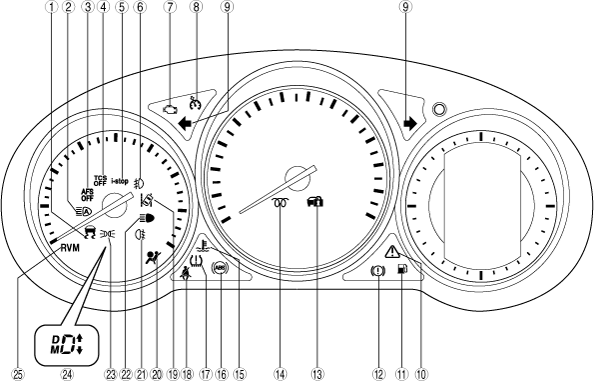
With TFT LCD display
ac5wzn00000947
|
|
No |
Warning/Indicator lights |
Name |
Comment |
|---|---|---|---|
|
1
|
|
TCS/DSC indicator light
|
—
|
|
2
|
|
High beam control system (HBC) indicator light (green)/high beam control (HBC) system warning light (amber)
|
With HBC System
|
|
3
|
|
AFS OFF indicator light
|
With AFS
|
|
4
|
|
TCS OFF indicator light
|
—
|
|
5
|
|
i-stop warning light (amber)/indicator light (green)
|
With i-stop system
|
|
6
|
|
Front fog light indicator light
|
With front fog light
|
|
7
|
|
Check engine light
|
—
|
|
8
|
|
Cruise main indicator light (amber)/cruise set indicator light (green)
|
With cruise control system
|
|
9
|
|
Turn signal/hazard warning indicator lights
|
—
|
|
10
|
|
Master warning light
|
—
|
|
11
|
|
Low fuel warning light
|
—
|
|
12
|
|
Brake system warning light
|
—
|
|
13
|
|
Security indicator light
|
—
|
|
14
|
|
Glow indicator light
|
SKYACTIV-D 2.2
|
|
15
|
|
High engine coolant temperature warning light (red)/low engine coolant temperature indicator light (blue)
|
—
|
|
16
|
|
ABS warning light
|
—
|
|
17
|
|
Tire pressure monitoring system warning light
|
With TPMS
|
|
18
|
|
Seat belt warning light
|
—
|
|
19
|
|
Lane departure warning system (LDWS) indicator light (green)/warning light (amber)
|
With LDWS
|
|
20
|
|
Air bag/front seat belt pretensioner system warning light
|
—
|
|
21
|
|
Rear fog light indicator light
|
With rear fog light
|
|
22
|
|
Headlight high-beam indicator light
|
—
|
|
23
|
|
Lights-on indicator light
|
—
|
|
24
|
|
Shift position indicator/gear position indicator
|
ATX
|
|
Gear shift indicator
|
MTX (with gear shift indicator)
|
||
|
25
|
|
Rear vehicle monitoring (RVM) system warning light (amber)/indicator light (green)
|
With rear vehicle monitoring system
|
Alarm Inspection
1. Connect the M-MDS to the DLC-2.
2. After vehicle identification, select the following from the M-MDS initialization screen.
3. Using “ALARM”, verify that the buzzer sounds.