 |
ac5wzw00001485
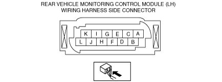
REAR VEHICLE MONITORING CONTROL MODULE INSPECTION
id092200014700
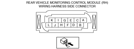
Rear Vehicle Monitoring Control Module Connector 12-pin Type
1. Disconnect the negative battery cable. (See NEGATIVE BATTERY CABLE DISCONNECTION/CONNECTION [SKYACTIV-G 2.0, SKYACTIV-G 2.5].)(See NEGATIVE BATTERY CABLE DISCONNECTION/CONNECTION [SKYACTIV-G 2.0, SKYACTIV-G 2.5 (WITHOUT i-stop)].)(See NEGATIVE BATTERY CABLE DISCONNECTION/CONNECTION [SKYACTIV-D 2.2].)
2. Remove the rear combination light. (See REAR COMBINATION LIGHT REMOVAL/INSTALLATION.)
3. Remove the rear bumper. (See REAR BUMPER REMOVAL/INSTALLATION.)
4. Connect the negative battery cable. (See NEGATIVE BATTERY CABLE DISCONNECTION/CONNECTION [SKYACTIV-G 2.0, SKYACTIV-G 2.5].)(See NEGATIVE BATTERY CABLE DISCONNECTION/CONNECTION [SKYACTIV-G 2.0, SKYACTIV-G 2.5 (WITHOUT i-stop)].)(See NEGATIVE BATTERY CABLE DISCONNECTION/CONNECTION [SKYACTIV-D 2.2].)
5. Verify that the voltages of each of the terminals are as indicated in the terminal voltage table (reference).
Terminal voltage table (reference)
Rear vehicle monitoring control module (RH)
ac5wzw00001485
|
|
Terminal |
Signal name |
Connected to |
Measurement conditions |
Voltage (V) |
Inspection item(s) |
|
|---|---|---|---|---|---|---|
|
A
|
CAN2_L
|
Rear vehicle monitoring CM (LH)
|
Because this terminal is for communication, determination using terminal voltage inspection is not possible.
|
|||
|
B
|
—
|
—
|
—
|
—
|
—
|
|
|
C
|
CAN2_H
|
Rear vehicle monitoring CM (LH)
|
Because this terminal is for communication, determination using terminal voltage inspection is not possible.
|
|||
|
D
|
—
|
—
|
—
|
—
|
—
|
|
|
E
|
—
|
—
|
—
|
—
|
—
|
|
|
F
|
Power position (1G1)
|
IG relay
|
Ignition switched ON (engine off or on)
|
B+
|
• C/U IG1 fuse
• IG relay
• Related wiring harness
|
|
|
Ignition switched off (LOCK) or ACC
|
1.0 or less
|
|||||
|
G
|
—
|
—
|
—
|
—
|
—
|
|
|
H
|
Ground
|
Body ground
|
Under any condition
|
1.0 or less
|
• Related wiring harness
|
|
|
I
|
MS-CAN_L
|
CAN communication related module
|
Because this terminal is for communication, determination using terminal voltage inspection is not possible.
|
|||
|
J
|
—
|
—
|
—
|
—
|
—
|
|
|
K
|
—
|
—
|
—
|
—
|
—
|
|
|
L
|
MS-CAN_H
|
CAN communication related module
|
Because this terminal is for communication, determination using terminal voltage inspection is not possible.
|
|||
Rear vehicle monitoring control module (LH)
ac5wzw00001486
|
|
Terminal |
Signal name |
Connected to |
Measurement conditions |
Voltage (V) |
Inspection item(s) |
|
|---|---|---|---|---|---|---|
|
A
|
—
|
—
|
—
|
—
|
—
|
|
|
B
|
—
|
—
|
—
|
—
|
—
|
|
|
C
|
RVM warning indicator light ground signal (RH)
|
RVM warning indicator light (RH)
|
Under any condition
|
1.0 or less
|
• RVM warning indicator light (RH)
• Related wiring harness
|
|
|
D
|
RVM warning indicator light signal (RH)
|
RVM warning indicator light (RH)
|
Turn off the RVM warning indicator light using the rear vehicle monitoring system simulation WRN_IND_R
|
1.0 or less
|
• RVM warning indicator light (RH)
• Related wiring harness
|
|
|
Turn on the RVM warning indicator light using the rear vehicle monitoring system simulation WRN_IND_R
|
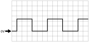
Wave pattern (See Inspection using an oscilloscope (reference).)
|
|||||
|
E
|
—
|
—
|
—
|
—
|
—
|
|
|
F
|
Power position (IG1)
|
IG relay
|
Ignition switched ON (engine off or on)
|
B+
|
• C/U IG1 fuse
• IG relay
• Related wiring harness
|
|
|
Ignition switched off (LOCK) or ACC
|
1.0 or less
|
|||||
|
G
|
RVM warning indicator light ground signal (LH)
|
RVM warning indicator light (LH)
|
Under any condition
|
1.0 or less
|
• RVM warning indicator light (LH)
• Related wiring harness
|
|
|
H
|
Ground
|
Body ground
|
Under any condition
|
1.0 or less
|
• Related wiring harness
|
|
|
I
|
CAN2_L
|
Rear vehicle monitoring CM (RH)
|
Because this terminal is for communication, determination using terminal voltage inspection is not possible.
|
|||
|
J
|
—
|
—
|
—
|
—
|
—
|
|
|
K
|
RVM warning indicator light signal (LH)
|
RVM warning indicator light (LH)
|
Turn off the RVM warning indicator light using the rear vehicle monitoring system simulation WRN_IND_L
|
1.0 or less
|
• RVM warning indicator light (LH)
• Related wiring harness
|
|
|
Turn on the RVM warning indicator light using the rear vehicle monitoring system simulation WRN_IND_L
|
Wave pattern (See Rear Vehicle Monitoring Control Module Connector 10-pin Type.)
|
|||||
|
L
|
CAN2_H
|
Rear vehicle monitoring CM (RH)
|
Because this terminal is for communication, determination using terminal voltage inspection is not possible.
|
|||
Inspection using an oscilloscope (reference)
Pattern 1
ac5wzw00002447
|
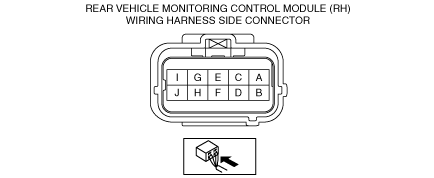
Rear Vehicle Monitoring Control Module Connector 10-pin Type
1. Disconnect the negative battery cable. (See NEGATIVE BATTERY CABLE DISCONNECTION/CONNECTION [SKYACTIV-G 2.0, SKYACTIV-G 2.5].)(See NEGATIVE BATTERY CABLE DISCONNECTION/CONNECTION [SKYACTIV-G 2.0, SKYACTIV-G 2.5 (WITHOUT i-stop)].)(See NEGATIVE BATTERY CABLE DISCONNECTION/CONNECTION [SKYACTIV-D 2.2].)
2. Remove the rear combination light. (See REAR COMBINATION LIGHT REMOVAL/INSTALLATION.)
3. Remove the rear bumper. (See REAR BUMPER REMOVAL/INSTALLATION.)
4. Connect the negative battery cable. (See NEGATIVE BATTERY CABLE DISCONNECTION/CONNECTION [SKYACTIV-G 2.0, SKYACTIV-G 2.5].)(See NEGATIVE BATTERY CABLE DISCONNECTION/CONNECTION [SKYACTIV-G 2.0, SKYACTIV-G 2.5 (WITHOUT i-stop)].)(See NEGATIVE BATTERY CABLE DISCONNECTION/CONNECTION [SKYACTIV-D 2.2].)
5. Verify that the voltages of each of the terminals are as indicated in the terminal voltage table (reference).
Terminal Voltage Table (Reference)
Rear vehicle monitoring control module (RH)
ac5wzw00006809
|
|
Terminal |
Signal name |
Connected to |
Measurement conditions |
Voltage (V) |
Inspection item(s) |
|
|---|---|---|---|---|---|---|
|
A
|
MS-CAN_H
|
CAN communication related module
|
Because this terminal is for communication, determination using terminal voltage inspection is not possible.
|
|||
|
B
|
—
|
—
|
—
|
—
|
—
|
|
|
C
|
—
|
—
|
—
|
—
|
—
|
|
|
D
|
MS-CAN_L
|
CAN communication related module
|
Because this terminal is for communication, determination using terminal voltage inspection is not possible.
|
|||
|
E
|
Ground
|
Body ground
|
Under any condition
|
1.0 or less
|
• Related wiring harness
|
|
|
F
|
—
|
—
|
—
|
—
|
—
|
|
|
G
|
Power position (1G1)
|
IG relay
|
Ignition switched ON (engine off or on)
|
B+
|
• C/U IG1 fuse
• IG relay
• Related wiring harness
|
|
|
Ignition switched off (LOCK) or ACC
|
1.0 or less
|
|||||
|
H
|
CAN2_H
|
Rear vehicle monitoring CM (LH)
|
Because this terminal is for communication, determination using terminal voltage inspection is not possible.
|
|||
|
I
|
—
|
—
|
—
|
—
|
—
|
|
|
J
|
CAN2_L
|
Rear vehicle monitoring CM (LH)
|
Because this terminal is for communication, determination using terminal voltage inspection is not possible.
|
|||
Rear vehicle monitoring control module (LH)
ac5wzw00006810
|
|
Terminal |
Signal name |
Connected to |
Measurement conditions |
Voltage (V) |
Inspection item(s) |
|
|---|---|---|---|---|---|---|
|
A
|
CAN2_H
|
Rear vehicle monitoring CM (RH)
|
Because this terminal is for communication, determination using terminal voltage inspection is not possible.
|
|||
|
B
|
RVM warning indicator light signal (LH)
|
RVM warning indicator light (LH)
|
Turn off the RVM warning indicator light using the rear vehicle monitoring system simulation WRN_IND_L
|
1.0 or less
|
• RVM warning indicator light (LH)
• Related wiring harness
|
|
|
Turn on the RVM warning indicator light using the rear vehicle monitoring system simulation WRN_IND_L
|
Wave pattern (See Inspection using an oscilloscope (reference).)
|
|||||
|
C
|
—
|
—
|
—
|
—
|
—
|
|
|
D
|
CAN2_L
|
Rear vehicle monitoring CM (RH)
|
Because this terminal is for communication, determination using terminal voltage inspection is not possible.
|
|||
|
E
|
Ground
|
Body ground
|
Under any condition
|
1.0 or less
|
• Related wiring harness
|
|
|
F
|
RVM warning indicator light ground signal (LH)
|
RVM warning indicator light (LH)
|
Under any condition
|
1.0 or less
|
• RVM warning indicator light (LH)
• Related wiring harness
|
|
|
G
|
Power position (IG1)
|
IG relay
|
Ignition switched ON (engine off or on)
|
B+
|
• C/U IG1 fuse
• IG relay
• Related wiring harness
|
|
|
Ignition switched off (LOCK) or ACC
|
1.0 or less
|
|||||
|
H
|
RVM warning indicator light ground signal (RH)
|
RVM warning indicator light (RH)
|
Under any condition
|
1.0 or less
|
• RVM warning indicator light (RH)
• Related wiring harness
|
|
|
I
|
RVM warning indicator light signal (RH)
|
RVM warning indicator light (RH)
|
Turn off the RVM warning indicator light using the rear vehicle monitoring system simulation WRN_IND_R
|
1.0 or less
|
• RVM warning indicator light (RH)
• Related wiring harness
|
|
|
Turn on the RVM warning indicator light using the rear vehicle monitoring system simulation WRN_IND_R
|
Wave pattern (See Rear Vehicle Monitoring Control Module Connector 10-pin Type.)
|
|||||
|
J
|
—
|
—
|
—
|
—
|
—
|
|
Inspection using an oscilloscope (reference)
Pattern 1
ac5wzw00002447
|