ON-BOARD DIAGNOSTIC [INSTRUMENT CLUSTER]
id092200021843
Outline
Malfunction detection function
DTC No. |
Warning/indicator light |
Description |
Fail-safe function |
Drive cycle |
Self test type*1 |
Memory function |
---|---|---|---|---|---|---|
B11D4:53*2
|
—
|
Laser sensor malfunction
|
×
|
—
|
C, D
|
×
|
U0001:88
|
—
|
Unit communication error (HS-CAN)
|
—
|
—
|
C, D
|
×
|
U0010:88
|
—
|
Unit communication error (MS-CAN)
|
—
|
—
|
C, D
|
×
|
U0100:00
|
—
|
Communication error with PCM
|
—
|
—
|
C, D
|
×
|
U0101:00*3
|
—
|
Communication error with TCM
|
—
|
—
|
C, D
|
×
|
U0114:00*4
|
—
|
4WD control module communication error
|
—
|
—
|
C, D
|
×
|
U0121:00
|
—
|
Communication error with DSC HU/CM
|
—
|
—
|
C, D
|
×
|
U0131:00
|
—
|
Communication error with EPS control module
|
—
|
—
|
C, D
|
×
|
U0140:00
|
—
|
Communication error with front body control module (FBCM)
|
—
|
—
|
C, D
|
×
|
U0142:00
|
—
|
Communication error with rear body control module (RBCM)
|
—
|
—
|
C, D
|
×
|
U0151:00
|
—
|
Communication error with SAS control module
|
—
|
—
|
C, D
|
×
|
U0182:00*5
|
—
|
Communication error with AFS control module
|
—
|
—
|
C, D
|
×
|
U0214:00
|
—
|
Communication error with start stop unit
|
—
|
—
|
C, D
|
×
|
U0232:00*6
|
—
|
Communication error with rear vehicle monitoring control module (RH)
|
—
|
—
|
C, D
|
×
|
U0233:00*7
|
—
|
Communication error with BSM control module (RH)
|
—
|
—
|
C, D
|
×
|
U0235:00*2
|
—
|
Communication error with laser sensor
|
—
|
—
|
C, D
|
×
|
U023A:00*8
|
—
|
Communication error with forward sensing camera (FSC)
|
—
|
—
|
C, D
|
×
|
U0300:00
|
—
|
Instrument cluster configuration error
|
—
|
—
|
C, D
|
×
|
U0401:68
|
—
|
Error signal received from PCM
|
—
|
—
|
C, D
|
×
|
U0402:68*3
|
—
|
Error signal received from transmission/transaxle
|
—
|
—
|
C, D
|
×
|
U0422:68
|
—
|
Error signal received from front body control module (FBCM)
|
—
|
—
|
C, D
|
×
|
U0433:00*2
|
—
|
Error signal received from laser sensor
|
×
|
—
|
C, D
|
×
|
U0433:68*2
|
—
|
Error signal received from laser sensor
|
×
|
—
|
C, D
|
×
|
U0515:68
|
—
|
Error signal received from start stop unit
|
—
|
—
|
C, D
|
×
|
U053B:00*8
|
—
|
Error signal received from forward sensing camera (FSC)
|
—
|
—
|
C, D
|
×
|
U2005:86
|
—
|
Error signal received from PCM
|
—
|
—
|
C, D
|
×
|
U2013:13
|
—
|
Cluster switch circuit malfunction
|
—
|
—
|
C, D
|
×
|
U2100:00
|
—
|
Instrument cluster configuration error
|
—
|
—
|
C, D
|
×
|
U2300:41
|
—
|
Instrument cluster configuration error
|
—
|
—
|
C, D
|
×
|
U2300:51
|
—
|
Instrument cluster configuration error
|
—
|
—
|
C, D
|
×
|
U2300:56
|
—
|
Instrument cluster configuration error
|
—
|
—
|
C, D
|
×
|
U2300:57
|
—
|
Instrument cluster configuration error
|
—
|
—
|
C, D
|
×
|
U3000:41
|
—
|
Malfunction inside instrument cluster
|
—
|
—
|
C, D
|
×
|
U3003:16
|
—
|
Low power supply voltage input to instrument cluster
|
—
|
—
|
C, D
|
×
|
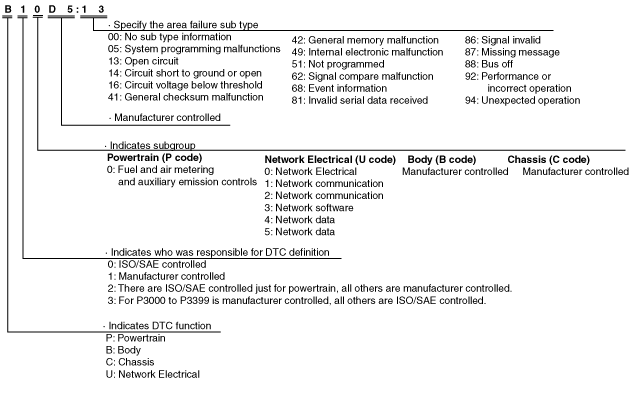
DTC 7-digit code definition
am6xun00000789
|
Status byte for DTC
ac5wzn00002008
|
Detection condition for the applicable DTC
DTC No. |
System malfunction location |
Detection condition |
---|---|---|
B11D4:53*1
|
Laser sensor malfunction
|
• Instrument cluster detects the following malfunctions
|
U0001:88
|
Module communication error (HS-CAN)
|
The instrument cluster detects a CAN bus communication line (HS-CAN) malfunction.
|
U0010:88
|
Unit communication error (MS-CAN)
|
The instrument cluster detects a CAN bus communication line (MS-CAN) malfunction.
|
U0100:00
|
Communication error with PCM
|
The instrument cluster cannot receive CAN signal from the PCM.
|
U0101:00*2
|
Communication error with TCM
|
The instrument cluster cannot receive CAN signal from the TCM for 1 s or more.
|
U0114:00*3
|
4WD control module communication error
|
The instrument cluster cannot receive CAN signal from the 4WD control module for 1 s or more.
|
U0121:00
|
Communication error with DSC HU/CM
|
The instrument cluster cannot receive CAN signal from the DSC HU/CM for 1 s or more.
|
U0131:00
|
Communication error with EPS control module
|
The instrument cluster could not receive CAN signal from the EPS control module for 1 s or more.
|
U0140:00
|
Communication error with front body control module (FBCM)
|
The instrument cluster cannot receive CAN signal from the front body control module (FBCM) for 5 s or more.
|
U0142:00
|
Communication error with rear body control module (RBCM)
|
The instrument cluster cannot receive CAN signal from the rear body control module (RBCM) for 5 s or more.
|
U0151:00
|
Communication error with SAS control module
|
The instrument cluster cannot receive CAN signal from the SAS control module for 2 s or more.
|
U0182:00*4
|
Communication error with AFS control module
|
The instrument cluster cannot receive CAN signal from the AFS control module for 5 s or more.
|
U0214:00
|
Communication error with start stop unit
|
The instrument cluster could not receive CAN signal from the start stop unit.
|
U0232:00*5
|
Communication error with rear vehicle monitoring control module (RH)
|
The instrument cluster cannot receive CAN signal from the rear vehicle monitoring control module (RH) for 5 s or more.
|
U0233:00*6
|
Communication error with BSM control module (RH)
|
The instrument cluster cannot receive CAN signal from the BSM control module (RH) for 1.5 s or more.
|
U0235:00*1
|
Communication error with laser sensor
|
The instrument cluster cannot receive CAN signal from the laser sensor for 1 s or more.
|
U023A:00*7
|
Communication error with forward sensing camera (FSC)
|
The instrument cluster cannot receive CAN signal from the forward sensing camera (FSC) for 1 s or more.
|
U0300:00
|
Instrument cluster configuration error
|
Instrument cluster configuration error (incorrect value write) detected.
|
U0401:68
|
Error signal received from PCM
|
The instrument cluster receives error signals from the PCM with the ignition switched ON (engine off or on).
|
U0402:68*2
|
Error signal received from transmission/transaxle
|
The instrument cluster received error signals from the transmission/transaxle for 1 s or more with the ignition switched ON (engine off or on).
|
U0422:68
|
Error signal received from front body control module (FBCM)
|
The instrument cluster receives error signals from the front body control module (FBCM) for 5 s or more with the ignition switched ON (engine off or on).
|
U0433:00*1
|
Error signal received from laser sensor
|
• Instrument cluster detects the following conditions:
* : Vehicle identification number (VIN): Except European (U.K.) specs. (JM0 KE****** 200001—, JM6 KE****** 200001—, JM8 KE****** 200001, JMZ KE****** 200001, KE10** 200001—), European (U.K.) specs. (JMZ KE****** 158745—)
|
U0433:68*1
|
Error signal received from laser sensor
|
Instrument cluster detects a malfunction in the laser sensor.
|
U0515:68
|
Error signal received from start stop unit
|
The instrument cluster receives error signals from the start stop unit with the ignition switched ON (engine off or on).
|
U053B:00*7
|
Error signal received from forward sensing camera (FSC)
|
The instrument cluster receives error signals from the forward sensing camera (FSC) for 1 s or more with the ignition switched ON (engine off or on).
|
U2005:86
|
Error signal received from PCM
|
The instrument cluster receives vehicle speed signal error from the PCM for 1 s or more with the ignition switched ON (engine off or on).
|
U2013:13
|
Cluster switch circuit malfunction
|
The instrument cluster detects an open circuit in the cluster switch circuit for 5 s or more with the ignition switched ON (engine off or on).
|
U2100:00
|
Instrument cluster configuration error
|
• Instrument cluster configuration error detected as follows:
|
U2300:41
|
Instrument cluster configuration error
|
Instrument cluster configuration error (data error) detected.
|
U2300:51
|
Instrument cluster configuration error
|
Instrument cluster configuration error (no configuration) detected.
|
U2300:56
|
Instrument cluster configuration error
|
Instrument cluster configuration error (incorrect value write) detected.
|
U2300:57
|
Instrument cluster configuration error
|
Instrument cluster configuration error (data size error) detected.
|
U3000:41
|
Malfunction inside instrument cluster
|
Malfunction inside instrument cluster detected.
|
U3003:16
|
Low power supply voltage input to instrument cluster
|
Instrument cluster power supply circuit voltage of 10 V or less is detected with the ignition switched ON (engine off or on).
|
Snapshot Data
Snapshot data table
Snapshot data item |
Unit |
Data contents |
Data read/use method |
Corresponding data monitor items |
|
---|---|---|---|---|---|
AAT
|
°C
|
°F
|
Ambient temperature
|
—
|
—
|
APP_STATUS
|
Accelerator Pedal Off/Under20%/Over20%/FAIL
|
Accelerator pedal position status
|
—
|
—
|
|
CFG_STATUS
|
Config Complete/Not Configured/Config Error
|
Instrument cluster configuration status
|
—
|
—
|
|
ECT_STATUS
|
Under 0 degrees C/0-Under 80 degrees C/Over 80 degrees C/FAIL
|
Engine coolant temperature status
|
—
|
—
|
|
IC_VPWR
|
V
|
Instrument cluster power supply voltage
|
When DTC is detected, instrument cluster displays power supply voltage value of instrument cluster in Mazda Modular Diagnostic System (M-MDS).
|
VPWR
|
|
IG-ON_TIMER
|
hh:mm:ss*1
|
Elapsed time since ignition was switched ON
|
When DTC is detected, instrument cluster displays elapsed time since ignition was switched on in Mazda Modular Diagnostic System (M-MDS).
|
—
|
|
PWR_MODE_KEY
|
Key Out/Key Recently Out/
Key Approved (Position 0)/
Post Accessory (Position 0)/
Accessory (Position 1)/
Post Ignition (Position 1)/
ignition On (Position 2)/
Running - Starting In Progress (Position 2)/Crank (Position 3)
|
• Key Out: Ignition switched to off
• Key Recently Out (Position 0): Elapsed time within 3 s since ignition was switched to off
• Accessory (Position 1): Ignition is switched to ACC
• Post Ignition (Position 2): Elapsed time within 3 s since ignition was switched ON
• Ignition On (Position 2): Ignition switched ON (engine off)
• Running (Position 2): Ignition switched ON (engine on)
• Running - Starting: Cranking condition
|
When DTC is detected, instrument cluster displays ignition switch status in Mazda Modular Diagnostic System (M-MDS).
|
—
|
|
RPM_STATUS
|
Engine Stop/Under1500rpm/Over1500rpm/FAIL
|
Engine speed status
|
When DTC is detected, instrument cluster displays engine speed in Mazda Modular Diagnostic System (M-MDS).
|
TACHOMTR
|
|
SHIFT_STATUS
|
P/N/
D/
R/
FAIL
|
Selector lever position status
|
When DTC is detected, instrument cluster displays selector lever position in Mazda Modular Diagnostic System (M-MDS).
|
—
|
|
TOTAL_DIST
|
Km
|
miles
|
Accumulated total traveled distance from completion of vehicle until instrument cluster detects DTC (Odometer value in instrument cluster)
|
The distance traveled when the instrument cluster detected a DTC can be calculated by performing the following procedure.
1. Verify the odometer value in the instrument cluster.
2. Verify the snap shot data item TOTAL_DIST.
3. Subtract 2 from 1.
|
—
|
TOTAL_TIME
|
hh:mm:ss*1
|
Accumulated total elapsed time since vehicle completion until instrument cluster detects a DTC
|
The elapsed time when the instrument cluster detected a DTC can be calculated by performing the following procedure.
1. Verify the PID item TOTAL_TIME of the instrument cluster.
2. Verify the snap shot data item TOTAL_TIME.
3. Subtract 2 from 1.
|
TOTAL_TIME
|
|
VPWR
|
V
|
Instrument cluster power supply voltage
|
—
|
VPWR
|
|
VSPD_STATUS
|
Stop/
0-10km/h/
Over10km/h/
FAIL
|
Vehicle speed status
|
When DTC is detected, instrument cluster displays vehicle speed in Mazda Modular Diagnostic System (M-MDS).
|
SPEEDOMTR
|
|
VSS
|
KPH, MPH
|
Vehicle speed
|
—
|
—
|
Data Monitor Function
PID/data monitor table
PID |
Unit/Operation |
Data contents |
Inspection item(s) |
---|---|---|---|
AFS_ST*1
|
Off/On
|
• Off: AFS not operated
• On: AFS operated
|
• AFS OFF switch
• AFS control module
|
AT_MAN_M_SW*2
|
Off/On/Reserved/Unknown
|
• Off: M range switch is off.
• On: M range switch is on.
• Unknown: M range switch signal is not determined.
|
M position switch
|
AT_S_DWN_SW*2
|
Off/On/Reserved/Unknown
|
• Off: Down switch switch is off.
• On: Down switch is on.
• Unknown: Down switch is not determined.
|
Down switch
|
AT_S_UP_SW*2
|
Off/On/Reserved/Unknown
|
• Off: Up switch is off.
• On: Up switch is on.
• Unknown: Up switch is not determined.
|
Up switch
|
BSM/RVM_SW*3
|
Off/On
|
• Off: Off: BSM OFF switch is off.
• On: BSM OFF switch is on.
|
BSM OFF switch
|
BSM/RVM_SW*4
|
Off/On
|
• Off: RVM OFF switch is off.
• On: RVM switch is on.
|
RVM switch
|
DSC_OFF_SW
|
Off/On
|
• Off: TCS OFF switch is off.
• On: TCS off switch is on.
|
TCS OFF switch
|
FUEL_GAUGE
|
L
|
Fuel gauge is displayed.
|
Fuel gauge (instrument cluster)
|
FUEL_SEN_M
|
ohm
|
Fuel gauge sender unit resistance is displayed.
|
• Fuel gauge sender unit
• Rear body control module (RBCM)
|
FUEL_SEN_S*5
|
ohm
|
Displays the fuel gauge sender unit (sub) resistance value.
|
• Fuel gauge sender unit (sub)
• Rear body control module (RBCM)
|
I_ILLUMI_M
|
Off (Day)/On (Night)
|
• Off (Day): TNS switch is off.
• On (Night): TNS switch is on.
|
• Instrument cluster
• Front body control module (FBCM)
|
I-ST_OFF_SW*6
|
Off/On
|
• Off: i-stop OFF switch is off.
• On: i-stop OFF switch is on.
|
i-stop OFF switch
|
LDWS_ON_SW*7
|
Off/On
|
• Off: LDWS switch is off.
• On: LDWS switch is on.
|
LDWS switch
|
MULTI_SW_ST
|
O.K./FAULT
|
• O.K.: Cluster switch is normal.
• FAULT: Cluster switch is malfunctioning.
|
Cluster switch
|
ODO_CNT
|
km, ft, mi
|
Displays the rolling count of the odometer.
|
Odometer (instrument cluster)
|
P_BRAKE_SW
|
Off/On
|
• Off: Parking brake not applied
• On: Parking brake applied
|
Parking brake switch
|
R_GEAR_SW
|
Off/On
|
ATX:
• On: Displays in the M-MDS but it does not operate.
MTX:
• Off: Back-up light switch is off.
• On: Back-up light switch is on.
|
ATX:
• Transaxle range sensor (TCM)
• TCM
MTX:
• Back-up light switch
• PCM
|
R_LMP
|
Off/On/Unknown/Fault
|
• Off: Back-up light is turned off.
• On: Back-up light is turned on.
• Unknown: Back-up light signal is not determined.
• Fault: Back-up light malfunction
|
ATX:
• Transaxle range sensor (TCM)
• TCM
• Instrument cluster
MTX:
• Back-up light switch
• PCM
• Instrument cluster
|
SPEEDOMTR
|
KPH, MPH
|
Vehicle speed is displayed. (100 %= 300 km/h {186 mph})
|
Speedometer (instrument cluster)
|
TACHOMTR
|
RPM
|
Displays the engine speed. (100 %= 10,000 rpm)
|
Tachometer (instrument cluster)
|
TOTAL_TIME
|
hh:mm:ss
|
Cumulative elapsed time since vehicle completion is displayed.
|
Instrument cluster
|
TPMS_CAL_SW
|
Off/On
|
• Off: Tire pressure monitoring system set switch is off.
• On: Tire pressure monitoring system set switch is on.
|
Tire pressure monitoring system set switch
|
VPWR
|
V
|
Displays the power supply voltage.
|
• Instrument cluster
• IG1 relay
• Battery
|
Active Command Modes Function
Simulation item |
Unit/Operation |
Data contents |
Output part name |
---|---|---|---|
ALARM
|
On/Off
|
• On: Warning alarm sounds.
• Off: Warning alarm does not sound.
|
Warning alarm (instrument cluster)
|
LCD_SEG
|
Off/On
|
Vehicles without TFT LCD display:
• Off: Turns off the LCD.
• On: Fully displays LCD.
Vehicles with TFT LCD display:
• Off: Turns off the LCD.
• On: Illuminates the LCD.
|
Vehicles without TFT LCD display:
• LCD (instrument cluster)
Vehicles with TFT LCD display:
• TFT LCD display (instrument cluster)
|
SPEEDOMTR
|
Off/60 Km/h/120 Km/h
|
European (L.H.D./U.K.), General (L.H.D./R.H.D.) specs., Australian specs.:
• Off: Moves speedometer needle to the bottom-most position.
• 60 Km/h: Moves speedometer needle to 61—66 km/h {38—41 mph}.
• 120 Km/h: Moves speedometer needle to 122—129 km/h {75.9—80.1 mph}.
General (L.H.D./R.H.D.) specs.:
• Off: Moves speedometer needle to the bottom-most position.
• 60 Km/h: Moves speedometer needle to 58—62 km/h {36—39 mph}.
• 120 Km/h: Moves speedometer needle to 117—123 km/h {72.8—76.4 mph}.
|
Speedometer (instrument cluster)
|
TACHOMTR
|
Off/3000 RPM/6000 RPM
|
• Off: Moves tachometer needle to the bottom-most position.
• 3000 RPM: Moves tachometer needle to approx. 3,050 rpm.
• 6000 RPM: Moves tachometer needle to approx. 6,100 rpm.
|
Tachometer (instrument cluster)
|
WL+IL
|
Off/On
|
• Off: Turns off all warning lights, indicator lights.
• On: Illuminates all warning lights, indicator lights.
|
Warning lights, indicator lights (instrument cluster)
|