 |
ac5wzw00001700
CLOCK INPUT/OUTPUT CHECK MODE
id092200031700
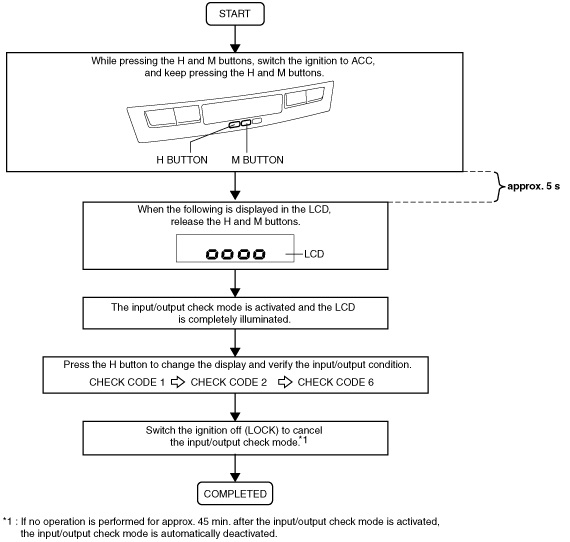
Activation procedure
ac5wzw00001700
|
Inspection
|
Item |
Check content |
|---|---|
|
All LCD illuminated
|
LCD indication
|
|
Check code 1
|
MS-CAN BUS OFF occurrence
|
|
Check code 2
|
Communication between instrument cluster
|
|
Check code 6
|
Ignition switch ON/OFF signal
|
All LCD illuminated
|
Inspection |
Display |
Action |
||
|---|---|---|---|---|
|
• Activate the clock input/output check mode.
• Are all segments and dots on the LCD illuminated?
|
 |
Yes
|
LCD display is normal.
|
|
|
No
|
Replace the clock.
(See CLOCK INSPECTION.)
|
|||
Check code 1
|
Inspection procedure |
Display |
Action |
|---|---|---|
|
1. Press the H button to display check code 1.
2. Verify the screen display.
|
 |
There is no MS-CAN BUS OFF error (normal)
|
 |
There is an MS-CAN BUS OFF error (malfunction)
Perform the malfunction diagnosis for the MS-CAN referring to the following:
|
Check code 2
|
Inspection procedure |
Display |
Action |
|
|---|---|---|---|
|
1. Press the H button to display check code 2.
2. Verify the screen display.
|
 |
There is no communication error between the instrument cluster.
|
|
 |
There is a communication error between the instrument cluster.
Perform the malfunction diagnosis for the MS-CAN referring to the following:
|
||
Check code 6
|
Inspection procedure |
Display |
Action |
||
|---|---|---|---|---|
|
Step 1
|
1. Press the H button to display check code 6.
2. Switch the ignition ON (engine off or on).
3. Verify the screen display.
|
 |
Go to the next step.
|
|
 |
Refer to the clock inspection and verify the terminal voltage at clock terminal A.
(See CLOCK INSPECTION.)
• Replace the clock if the voltage is B+.
(See CLOCK REMOVAL/INSTALLATION.)
• Inspect the following parts if the voltage is 1.0 V or less.
|
|||
|
Step 2
|
1. Switch the ignition off (LOCK).
2. Verify the screen display.
|
|
Ignition switch ON/OFF signal is normal.
|
|
|
Refer to the clock inspection and verify the terminal voltage at clock terminal A.
(See CLOCK INSPECTION.)
• Replace the clock if the voltage is 1.0 V or more.
(See CLOCK REMOVAL/INSTALLATION.)
• Inspect the following parts if the voltage is B+.
|
|||