 |
ac5wzw00004531
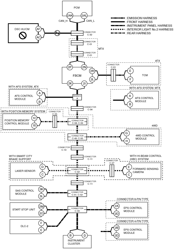
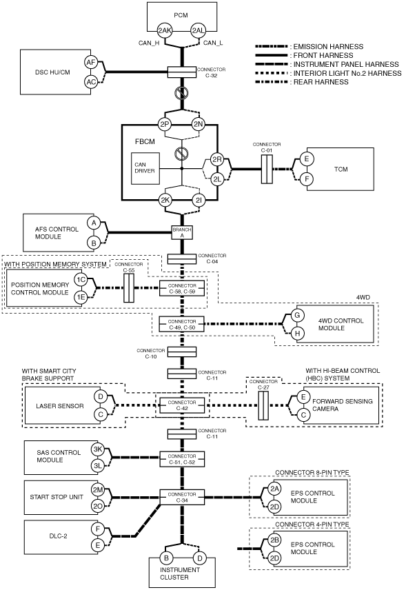
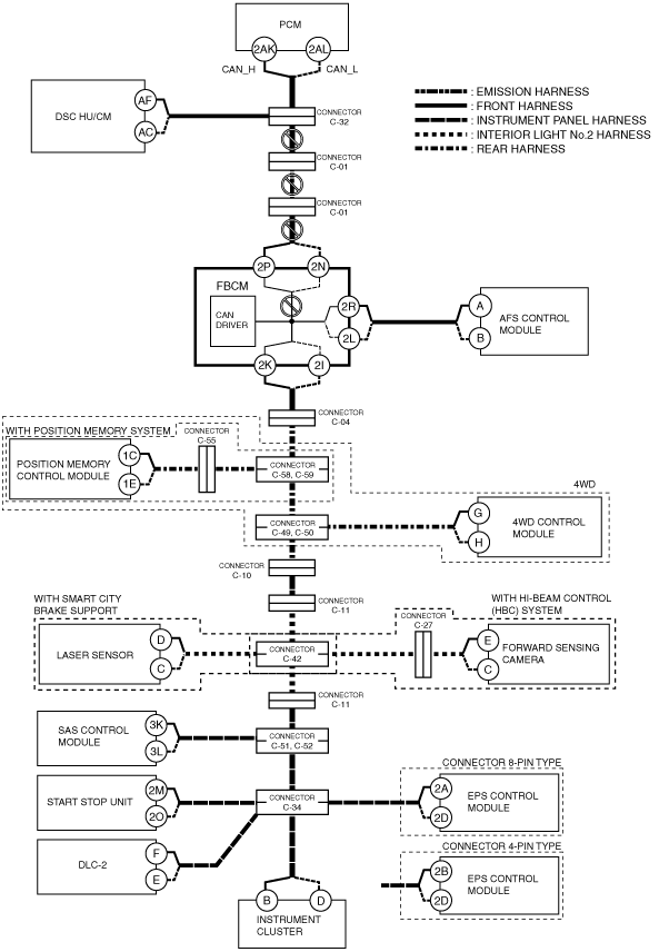
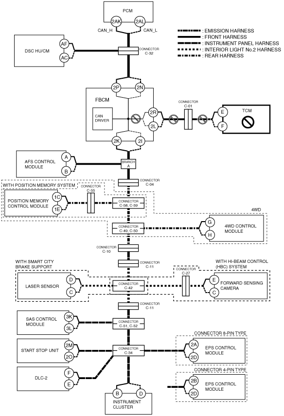
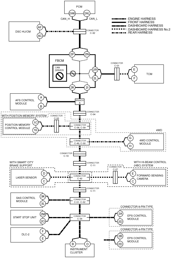
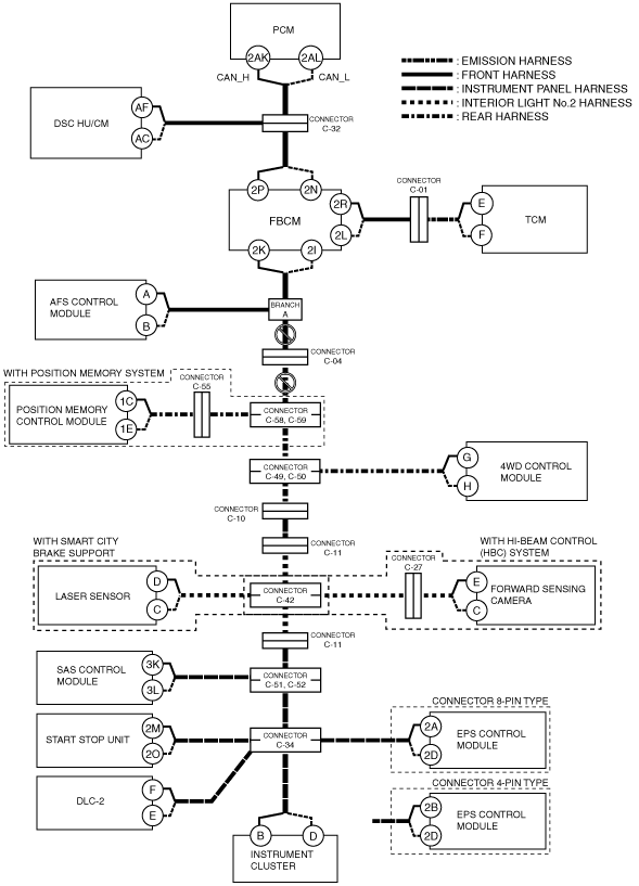
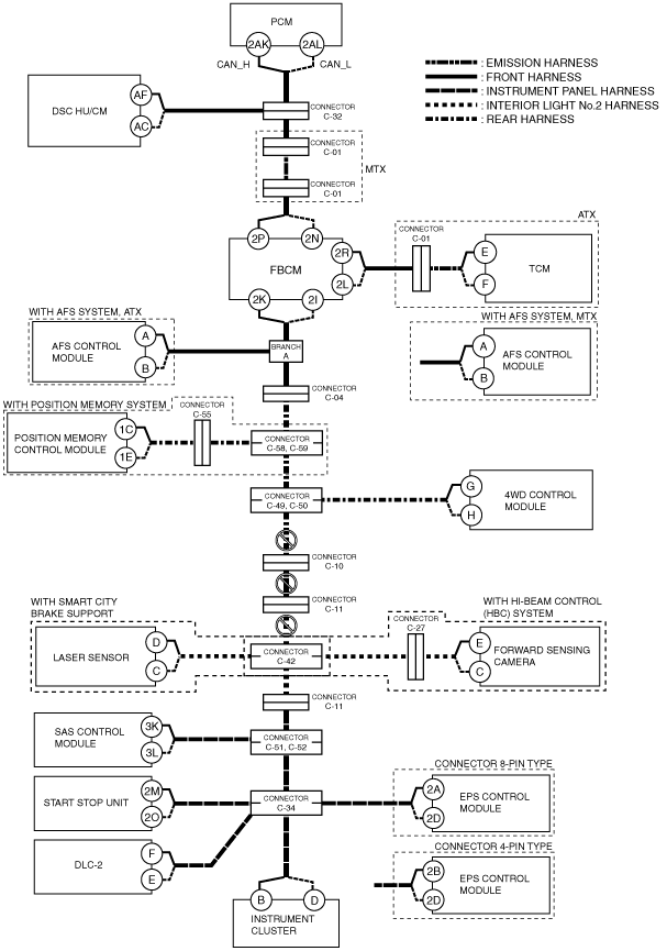
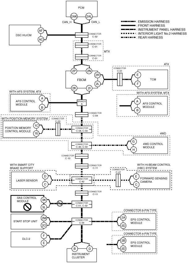
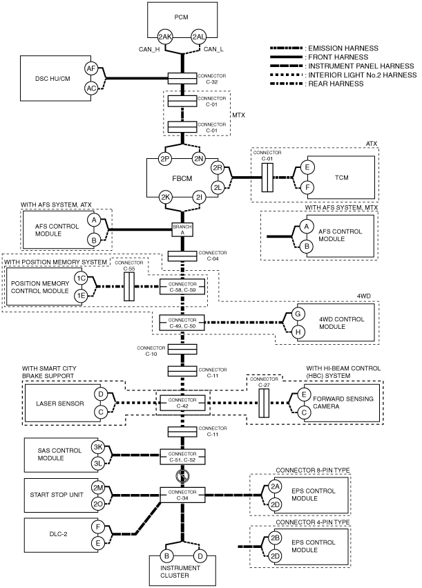
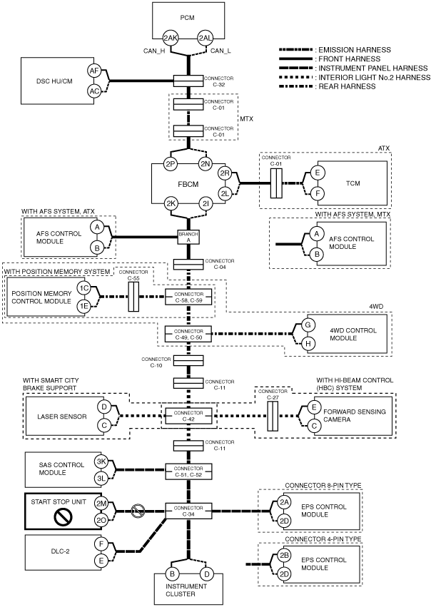
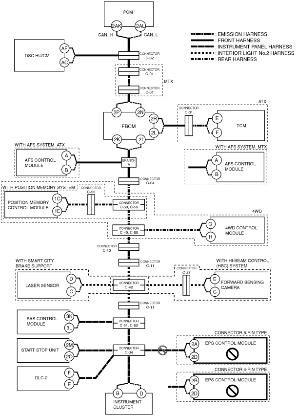
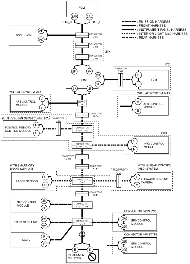
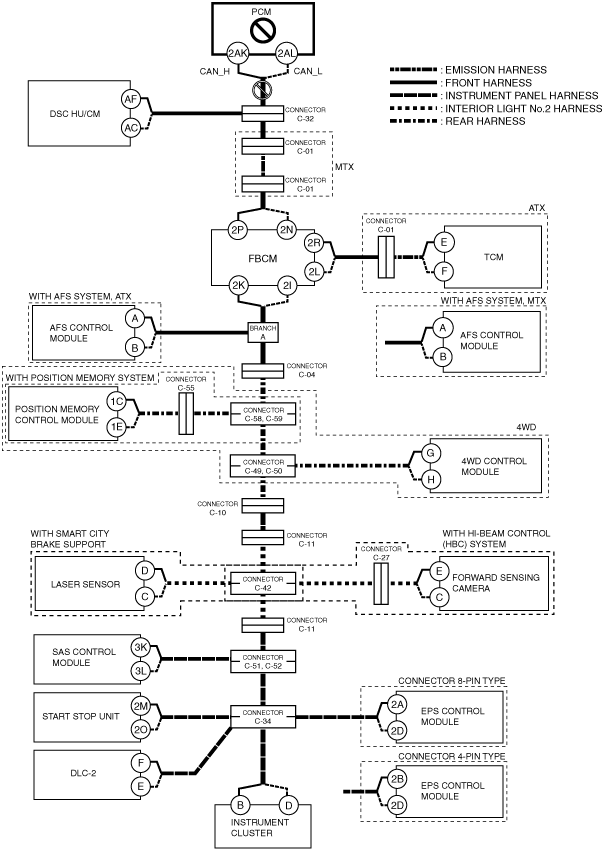
DETERMINING OPEN CIRCUIT LOCATION (HS-CAN) [SKYACTIV-D 2.2 (R.H.D.)]
id100206000400
1. Verify the CAN system-related module DTCs and the failed module on the M-MDS screen.
2. Apply the communication error DTC and the failed module to DTC Output Pattern And Malfunctioning Location, and select the possible cause for the diagnostic result and the reference for the inspection item. (See DTC Output Pattern And Malfunctioning Location.)
3. Inspect the possible cause and inspection item of the applicable malfunctioning part.
4. After repairs, return to CONTROLLER AREA NETWORK (CAN) MALFUNCTION DIAGNOSIS FLOW [SKYACTIV-D 2.2 (R.H.D.)], and verify that the repairs have been completed. (See CONTROLLER AREA NETWORK (CAN) MALFUNCTION DIAGNOSIS FLOW [SKYACTIV-D 2.2 (R.H.D.)].)
DTC Output Pattern And Malfunctioning Location
|
M-MDS display |
DTC output pattern and malfunctioning location |
||||||||||||||||||||
|---|---|---|---|---|---|---|---|---|---|---|---|---|---|---|---|---|---|---|---|---|---|
|
DTC output module |
DTC |
||||||||||||||||||||
|
PCM
(PCM)
|
U0101:00
|
|
|
|
×
|
|
|
|
|
|
|
|
|
|
|
|
|
|
|
||
|
U0120:00
|
|
|
|
|
|
|
|
|
|
|
|
|
|
|
|
×
|
|
|
|||
|
U0121:00
|
|
×
|
|
|
|
|
|
|
|
|
|
|
|
|
|
|
|
|
|||
|
U0131:00
|
|
|
|
|
|
|
|
|
|
|
|
|
|
|
|
|
×
|
|
|||
|
U0140:00
|
|
|
|
|
×
|
|
|
|
|
|
|
|
|
|
|
|
|
|
|||
|
U0151:00
|
|
|
|
|
|
|
|
|
|
|
|
|
|
×
|
|
|
|
|
|||
|
U0155:00
|
|
|
|
|
|
|
|
|
|
|
|
|
|
|
|
|
|
×
|
|||
|
U0235:00
|
|
|
|
|
|
|
|
|
|
|
×
|
|
|
|
|
|
|
|
|||
|
ABS
(DSC HU/CM)
|
U0100:00
|
×
|
|
|
|
|
|
|
|
|
|
|
|
|
|
|
|
|
|
||
|
U0101:00
|
|
|
|
×
|
|
|
|
|
|
|
|
|
|
|
|
|
|
|
|||
|
U0114:00
|
|
|
|
|
|
|
|
|
|
|
×
|
|
|
|
|
|
|
|
|
||
|
U0131:00
|
|
|
|
|
|
|
|
|
|
|
|
|
|
|
|
×*8
|
×*7
|
|
|||
|
U0154:00
|
|
|
|
|
|
|
|
|
|
|
|
|
|
×
|
|
|
|
|
|||
|
U0155:00
|
|
|
|
|
|
|
|
|
|
|
|
|
|
|
|
|
|
×
|
|||
|
U0235:00
|
|
|
|
|
|
|
|
|
|
|
×
|
|
|
|
|
|
|
|
|||
|
TCM*1
(TCM)
|
U0100:00
|
×
|
|
×
|
|
|
|
|
|
|
|
|
|
|
|
|
|
|
|
||
|
U0121:00
|
|
×
|
×
|
|
|
|
|
|
|
|
|
|
|
|
|
|
|
|
|||
|
U0141:00
|
|
|
|
|
×
|
|
|
|
|
|
|
|
|
|
|
|
|
|
|||
|
U0155:00
|
|
|
|
|
|
|
|
|
|
|
|
|
|
|
|
|
|
×
|
|||
|
F_BCM
(Front body control module (FBCM))
|
U0100:00
|
×
|
|
×
|
|
|
|
|
|
|
|
|
|
|
|
|
|
|
|
||
|
U0101:00
|
|
|
|
×
|
|
|
|
|
|
|
|
|
|
|
|
|
|
|
|||
|
U0121:00
|
|
×
|
×
|
|
|
|
|
|
|
|
|
|
|
|
|
|
|
|
|||
|
U0151:00
|
|
|
|
|
|
|
|
|
|
|
|
|
|
×
|
|
|
|
|
|||
|
U0155:00
|
|
|
|
|
|
|
|
|
|
|
|
|
|
|
|
|
|
×
|
|||
|
U0214:00
|
|
|
|
|
|
|
|
|
|
|
|
|
|
|
|
×
|
|
|
|||
|
U0515:00
|
|
|
|
|
|
|
|
|
|
|
|
|
|
×
|
|
|
|
|
|||
|
AFS*2
(AFS control module)
|
U0100:00
|
×
|
|
×
|
|
|
×*1
|
|
|
|
|
|
|
|
|
|
|
|
|
|
|
|
U0131:00
|
|
|
|
|
|
|
|
|
|
|
|
|
|
|
|
|
|
|
×
|
|
|
|
U0140:00
|
|
|
|
|
×
|
×*1
|
|
|
|
|
|
|
|
|
|
|
|
|
|
|
|
|
U0155:00
|
|
|
|
|
|
|
|
|
|
|
|
|
|
|
|
|
|
|
|
×
|
|
|
DSM*3
(Position memory control module)
|
U0100:00
|
×
|
|
×
|
|
|
×
|
|
×
|
|
|
|
|||||||||
|
U0101:00
|
|
|
|
×
|
|
×
|
|
×
|
|
|
|
||||||||||
|
U0151:00
|
|
|
×
|
||||||||||||||||||
|
U0155:00
|
|
|
×
|
||||||||||||||||||
|
U0214:00
|
|
|
×
|
||||||||||||||||||
|
4X4*4
(4WD control module)
|
U0100:00
|
×
|
|
×
|
|
|
×
|
|
×
|
|
×
|
|
|
|
|
|
|
|
|
|
|
|
U0101:00
|
|
|
|
×
|
|
×
|
|
×
|
|
×
|
|
|
|
|
|
|
|
|
|
|
|
|
U0121:00
|
|
×
|
×
|
|
|
×
|
|
×
|
|
|
|
|
|
|
|
|
|
|
|
|
|
|
SCBS*5
(Laser sensor)
|
U0100:00
|
×
|
|
×
|
|
|
×
|
|
×
|
|
×
|
|
|
|
|
|
|
|
|
|
|
|
U0121:00
|
|
×
|
×
|
|
|
×
|
|
×
|
|
×
|
|
|
|
|
|
|
|
|
|
|
|
|
U0131:00
|
|
|
|
|
|
|
|
|
|
|
|
|
|
|
|
|
|
|
×
|
|
|
|
U0155:00
|
|
|
|
|
|
|
|
|
|
|
|
|
|
|
|
|
|
|
|
×
|
|
|
FSC*6
(Forward sensing camera)
|
U0100:00
|
×
|
|
×
|
|
|
×
|
|
×
|
|
×
|
|
|
|
|
|
|
|
|
|
|
|
U0121:00
|
|
×
|
×
|
|
|
×
|
|
×
|
|
×
|
|
|
|
|
|
|
|
|
|
|
|
|
U0131:00
|
|
|
|
|
|
|
|
|
|
|
|
|
|
|
|
|
|
|
×
|
|
|
|
U0140:00
|
|
|
|
|
×
|
×
|
|
×
|
|
×
|
|
|
|
|
|
|
|
|
|
|
|
|
U0155:00
|
|
|
|
|
|
|
|
|
|
|
|
|
|
|
|
|
|
|
|
×
|
|
|
U0214:00
|
|
|
|
|
|
|
|
|
|
|
|
|
|
|
|
|
|
×
|
|
|
|
|
RCM
(SAS control module)
|
U0155:00
|
|
|
|
|
|
|
|
|
|
|
|
|
|
|
|
|
|
|
|
×
|
|
SSU
(Start stop unit)
|
U0100:00
|
×
|
|
×
|
|
|
×
|
|
×
|
|
×
|
|
|
|
|
×
|
|
×
|
|
|
|
|
U0101:00
|
|
|
|
×
|
|
×
|
|
×
|
|
×
|
|
|
|
|
×
|
|
×
|
|
|
|
|
|
U0121:00
|
|
×
|
×
|
|
|
×
|
|
×
|
|
×
|
|
|
|
|
×
|
|
×
|
|
|
|
|
|
U0121:87
|
|
×
|
×
|
|
|
×
|
|
×
|
|
×
|
|
|
|
|
×
|
|
×
|
|
|
|
|
|
U0131:00
|
|
|
|
|
|
|
|
|
|
|
|
|
|
|
|
|
|
|
×
|
|
|
|
U0140:00
|
|
|
|
|
×
|
×
|
|
×
|
|
×
|
|
|
|
|
×
|
|
×
|
|
|
|
|
|
U0146:00
|
|
|
|
|
|
|
|
|
|
|
|
|
|
|
|
|
|
|
|
×
|
|
|
U0151:00
|
|
|
|
|
|
|
|
|
|
|
|
|
|
|
|
×
|
×
|
|
|
|
|
|
U0155:00
|
|
|
|
|
|
|
|
|
|
|
|
|
|
|
|
|
|
|
|
×
|
|
|
EPS
(EPS control module)
|
U0100:00
|
×
|
|
×
|
|
|
×
|
|
×
|
|
×
|
|
|
|
|
×
|
|
×
|
|
|
|
|
U0121:00
|
|
×
|
×
|
|
|
×
|
|
×
|
|
×
|
|
|
|
|
×
|
|
×
|
|
|
|
|
|
U0155:00
|
|
|
|
|
|
|
|
|
|
|
|
|
|
|
|
|
|
|
|
×
|
|
|
IC
(Instrument cluster)
|
U0100:00
|
×
|
|
×
|
|
|
×
|
|
×
|
|
×
|
|
|
|
|
×
|
|
×
|
|
|
|
|
U0101:00
|
|
|
|
×
|
|
×
|
|
×
|
|
×
|
|
|
|
|
×
|
|
×
|
|
|
|
|
|
U0114:00
|
|
|
|
|
|
|
|
|
|
|
×
|
|
|
|
×
|
|
×
|
|
|
|
|
|
U0121:00
|
|
×
|
×
|
|
|
×
|
|
×
|
|
×
|
|
|
|
|
×
|
|
×
|
|
|
|
|
|
U0131:00
|
|
|
|
|
|
|
|
|
|
|
|
|
|
|
|
|
|
|
×
|
|
|
|
U0140:00
|
|
|
|
|
×
|
×
|
|
×
|
|
×
|
|
|
|
|
×
|
|
×
|
|
|
|
|
|
U0151:00
|
|
|
|
|
|
|
|
|
|
|
|
|
|
|
|
×
|
×
|
|
|
|
|
|
U0182:00
|
|
|
|
|
|
×*9
|
×
|
×
|
|
×
|
|
|
|
|
×
|
|
×
|
|
|
|
|
|
U0214:00
|
|
|
|
|
|
|
|
|
|
|
|
|
|
|
|
|
|
×
|
|
|
|
|
U0235:00
|
|
|
|
|
|
|
|
|
|
|
|
|
×
|
|
×
|
|
×
|
|
|
|
|
|
U023A:00
|
|
|
|
|
|
|
|
|
|
|
|
|
|
×
|
×
|
|
×
|
|
|
|
|
|
M-MDS display module
|
[Fail] display pattern
|
||||||||||||||||||||
|
PCM
|
×
|
|
×
|
|
|
×
|
|
×
|
|
×
|
×
|
|
|
×
|
|
×
|
|
|
|
||
|
ABS
|
|
×
|
×
|
|
|
×
|
|
×
|
|
×
|
×
|
|
|
×
|
|
×
|
|
|
|
||
|
TCM*1
|
|
|
|
×
|
|
×
|
|
×
|
|
×
|
×
|
|
|
×
|
|
×
|
|
|
|
||
|
F_BCM
|
|
|
|
|
×
|
×
|
|
×
|
|
×
|
×
|
|
|
×
|
|
×
|
|
|
|
||
|
AFS*2
|
|
|
|
|
|
×*9
|
×
|
×
|
|
×
|
×
|
|
|
×
|
|
×
|
|
|
|
||
|
DSM*3
|
|
|
|
|
|
|
|
|
×
|
×
|
×
|
|
|
×
|
|
×
|
|
|
|
||
|
4X4*4
|
|
|
|
|
|
|
|
|
|
|
×
|
×
|
|
|
×
|
|
×
|
|
|
|
|
|
SCBS*5
|
|
|
|
|
|
|
|
|
|
|
×
|
|
×
|
|
×
|
|
|
|
|||
|
FSC*6
|
|
|
|
|
|
|
|
|
|
|
|
×
|
×
|
|
×
|
|
|
|
|||
|
RCM
|
|
|
|
|
|
|
|
|
|
|
|
|
|
×
|
×
|
|
|
|
|||
|
SSU
|
|
|
|
|
|
|
|
|
|
|
|
|
|
|
|
×
|
|
|
|||
|
EPS
|
|
|
|
|
|
|
|
|
|
|
|
|
|
|
|
|
×
|
|
|||
|
IC
|
|
|
|
|
|
|
|
|
|
|
|
|
|
|
|
|
|
×
|
|||
|
Possible cause and inspection item
|
|||||||||||||||||||||
A
Possible cause
System wiring diagram
ac5wzw00004531
|
Inspection item
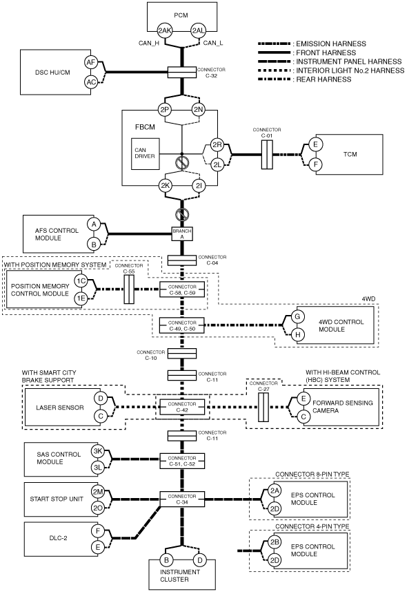
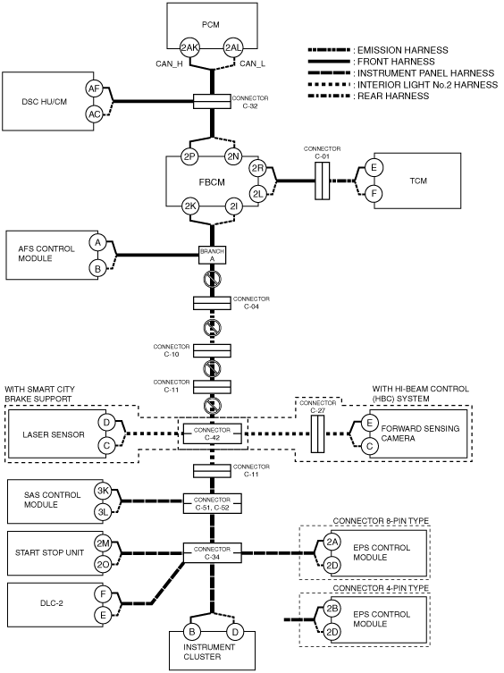
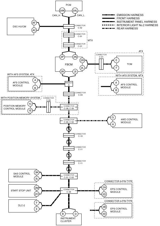
B
Possible cause
System wiring diagram
ac5wzw00004532
|
Inspection item
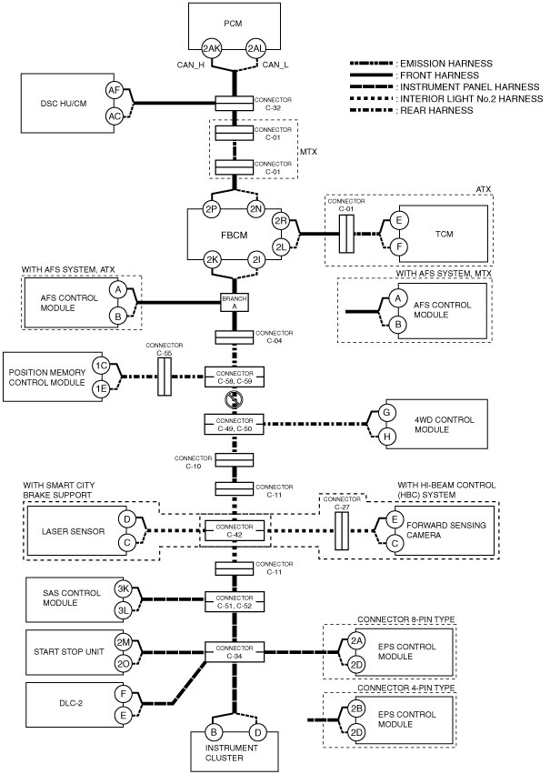
C
ATX
System wiring diagram
ac5wzw00004533
|
MTX
System wiring diagram
ac5wzw00004534
|
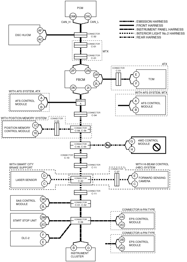
D
Possible cause
System wiring diagram
ac5wzw00004535
|
Inspection item
E
Possible cause
System wiring diagram
ac5wzw00004536
|
Inspection item
F
Possible cause
System wiring diagram
ac5wzw00004537
|
Inspection item
G
ATX
System wiring diagram
ac5wzw00004539
|
MTX
System wiring diagram
ac5wzw00004540
|
H
4WD (ATX)
System wiring diagram
ac5wzw00004541
|
2WD (ATX)
System wiring diagram
ac5wzw00004542
|
I
Possible cause
System wiring diagram
ac5wzw00004546
|
Inspection item
J
Possible cause
System wiring diagram
ac5wzw00004544
|
Inspection item
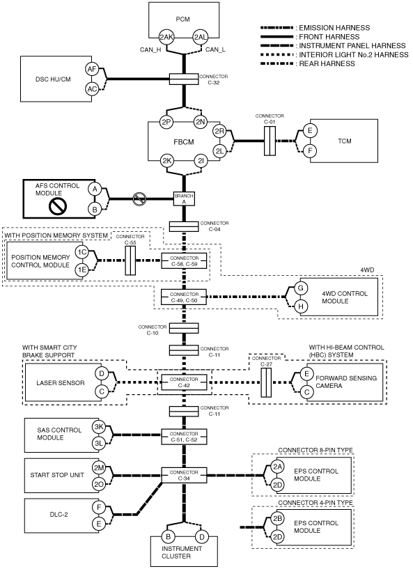
K
Possible cause
System wiring diagram
ac5wzw00004543
|
Inspection item
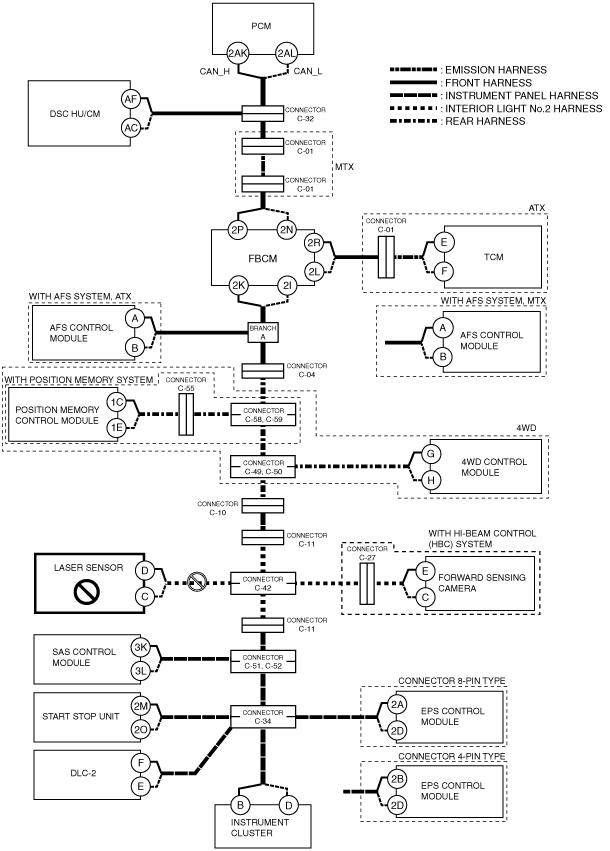
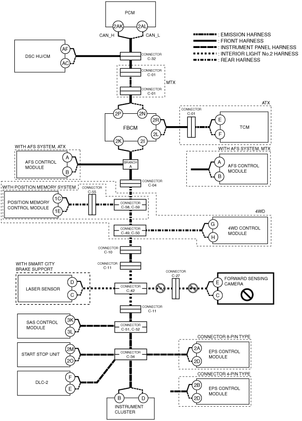
L
With smart city brake support or hi-beam control (HBC) system
System wiring diagram
ac5wzw00004547
|
Without smart city brake support or hi-beam control (HBC) system
System wiring diagram
ac5wzw00004548
|
M
Possible cause
System wiring diagram
ac5wzw00004549
|
Inspection item
N
Possible cause
System wiring diagram
ac5wzw00004550
|
Inspection item
O
Possible cause
System wiring diagram
ac5wzw00004551
|
Inspection item
P
Possible cause
System wiring diagram
ac5wzw00004552
|
Inspection item
Q
Possible cause
System wiring diagram
ac5wzw00004553
|
Inspection item
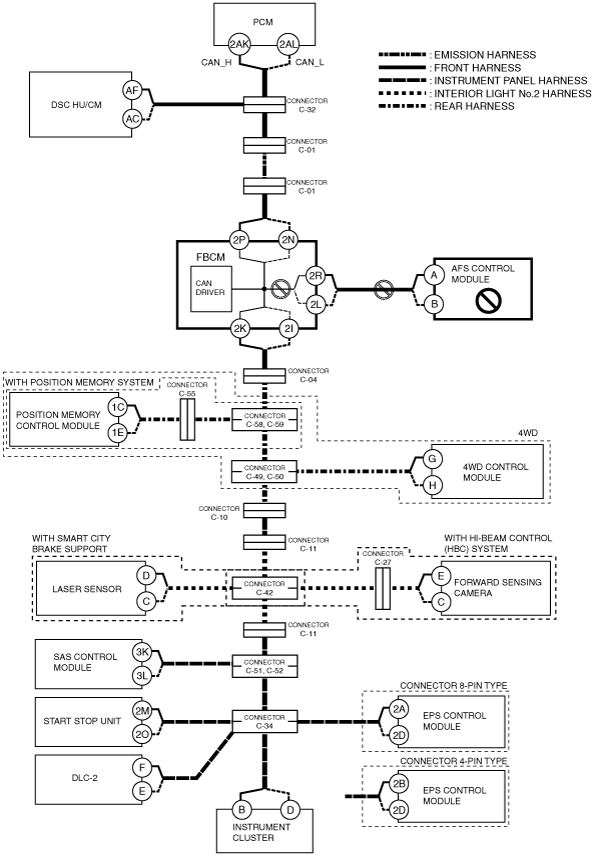
R
Possible cause
System wiring diagram
ac5wzw00006901
|
Inspection item
S
Possible cause
System wiring diagram
ac5wzw00006902
|
Inspection item
T
Possible cause
System wiring diagram
ac5wzw00006903
|
Inspection item