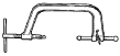
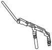
49 0636 100B
Valve spring lifter arm
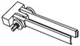
49 B012 0A2A
Pivot
49 JE02 0A2
Universal valve tool
[Europe only]
49 B012 016
Attachment

—
—
CYLINDER HEAD ASSEMBLY (I)
id011000504300
Special Service Tool (SST)
|
49 0636 100B
Valve spring lifter arm
|
|
49 B012 0A2A
Pivot
|
|
49 JE02 0A2
Universal valve tool
[Europe only]
|
|
|
49 B012 016
Attachment
|
|
—
|
—
|
||
1. Assemble in the order indicated in the table.
bp25ue00000080
|
|
1
|
Lower valve spring seat
|
|
2
|
Valve seal
(See Valve Seal Assembly Note.)
|
|
3
|
Valve
|
|
4
|
Valve spring
(See Valve Spring Assembly Note.)
|
|
5
|
Upper valve spring seat
|
|
6
|
Valve keeper
(See Valve Keeper Assembly Note.)
|
|
7
|
Blind cover
(See Blind cover Assembly Note.)
|
|
8
|
Hanger bracket
|
Valve Seal Assembly Note
1. Press on the valve seal to the valve guide using the SST by hand.
bpe5ue00000043
|
Valve Spring Assembly Note
bp25ue00000035
|
1. Assemble the valve spring with the small diameter side of the valve spring facing upward.
Valve Keeper Assembly Note
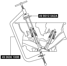
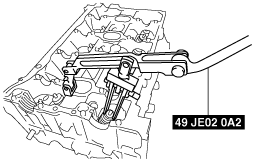
1. Install the valve keeper using the SST.
When using the SSTs (49 0636 100B, 49 B012 0A2A)
bpe1ze00000020
|
When using the SST (49 JE02 0A2) (Europe only)
bpe1ze00000035
|
Blind cover Assembly Note
1. Assemble the new gasket so that the identification tab is on the rear side of the engine and the painted surface is facing the cylinder head side.
bp25ue00000081
|
2. Assemble the blind cover so that the arrow is facing the upper surface of the cylinder head.