49 E011 1A0
Ring gear brake set
—
—
TIMING CHAIN DISASSEMBLY
id011000505500
Special Service Tool (SST)
|
49 E011 1A0
Ring gear brake set
|
|
—
|
—
|
am3uuw00008837
|
am3uuw00009029
|
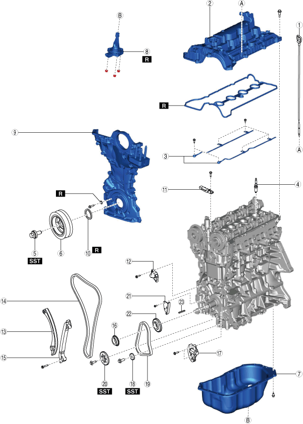
1. Disassemble in the order indicated in the table.
bp25ue00000046
|
|
1
|
Dipstick
|
|
2
|
Cylinder head cover
|
|
3
|
Oil shower pipe
|
|
4
|
Spark plug
|
|
5
|
Crankshaft pulley lock bolt
|
|
6
|
Crankshaft pulley
|
|
7
|
Oil pan
(See Oil Pan Disassembly Note.)
|
|
8
|
Oil level sensor
|
|
9
|
Engine front cover
|
|
10
|
Front oil seal
|
|
11
|
Chain guide (No.1)
|
|
12
|
Chain tensioner
|
|
13
|
Tensioner arm
|
|
14
|
Timing chain
|
|
15
|
Chain guide (No.2)
|
|
16
|
Crankshaft sprocket
|
|
17
|
Oil pump chain tensioner
|
|
18
|
Balancer shaft sprocket
|
|
19
|
Oil pump chain
|
|
20
|
Oil pump driven sprocket
|
|
21
|
Oil pump chain guide
|
|
22
|
Oil pump drive sprocket
|
|
23
|
Key
|
Crankshaft Pulley Lock Bolt Disassembly Note
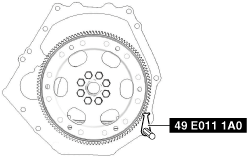
1. Hold the crankshaft using the SST.
bp26ze00000014
|
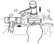
2. Remove the crankshaft pulley lock bolt.
Oil Pan Disassembly Note
1. Remove the oil pan using a separator tool.
adejjw00003946
|
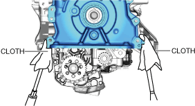
Engine Front Cover Disassembly Note
1. Remove the engine front cover installation bolts.
2. Using a screwdriver wrapped in a cloth, peel the sealant away a little at a time, and remove the engine front cover.
bp25ue00000048
|
bp25ue00000049
|
Front Oil Seal Disassembly Note
1. Remove the oil seal using a flathead screwdriver with the tip protected by a clean cloth.
bpe2ue00000100
|
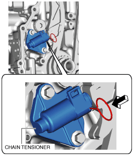
Chain Tensioner Disassembly Note
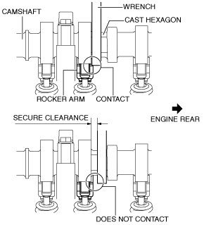
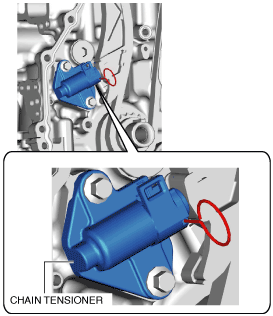
1. Verify the chain tensioner shape and identify the chain tensioner type.
ac4ccw00002689
|
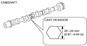
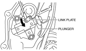
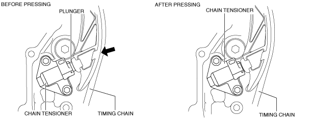
2. While moving the exhaust camshaft back and forth in the direction of the arrow using a wrench on the cast hexagon, press down the link plate of the timing chain tensioner using a precision screwdriver and release the plunger lock. (Chain tensioner (type A))
bp25ue00000050
|
am3uuw00008854
|
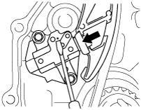
3. Push back the plunger slowly in the direction shown in the figure with the link plate still pushed down. (Chain tensioner (type A))
am3uuw00008855
|
4. Remove the screwdriver from the link plate with the plunger still pushed down. (Chain tensioner (type A))
5. Release the force slightly from the plunger, and move it back and forth 2—3 mm {0.08—0.11 in}. (Chain tensioner (type A))
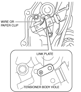
6. Insert a wire with an approx. diameter of 1.5 mm {0.059 in} or a paper clip where the link plate hole and the tensioner body hole overlap to secure the link plate and lock the plunger. (Chain tensioner (type A))
am3uuw00008856
|
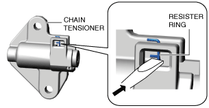
7. Loosen the chain tensioner using the following procedure: (Chain tensioner (type B))
amxzzw00003020
|
amxzzw00003021
|
amxuuw00004405
|
amxzzw00003022
|
8. Remove the chain tensioner.
Oil Pump Chain Disassembly Note
1. Hold the crankshaft using the SST.
bp26ze00000014
|
2. Slightly loosen the balancer shaft sprocket and oil pump driven sprocket installation bolts.
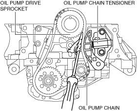
3. Set a cloth wrapped flathead screwdriver in the gap between the oil pump drive sprocket and the oil pump chain as shown in the figure.
bp25ue00000051
|
4. Move the screwdriver in the direction of the arrow and press the oil pump chain, and then press on the plunger of the oil pump chain tensioner.
bp25ue00000052
|
5. Insert a wire with an approx. diameter of 1.4 mm {0.055 in} or a paper clip into the body hole of the oil pump chain tensioner with the plunger pressed.
bp25ue00000053
|
6. Remove the oil pump chain tensioner.
7. Remove the oil pump chain and balancer shaft sprocket as a single unit.
8. Remove the oil pump driven sprocket.