LOW CLUTCH CLEARANCE MEASUREMENT/ADJUSTMENT
id051700664500
Preparation Before Servicing
1. Print out the measurement/adjustment value input sheet. (See MEASUREMENT/ADJUSTMENT VALUE INPUT SHEET [EW6A-EL/EW6AX-EL].)(See MEASUREMENT/ADJUSTMENT VALUE INPUT SHEET [FW6A-EL/FW6AX-EL].)
-
Note
-
• When performing the measurement/adjustment, input the measured and calculated values into the measurement/adjustment value input sheet.
• When performing the other measurements/adjustments, if the measurement/adjustment value input sheet has been printed out, use the printed sheet.
Low Clutch Clearance Measurement
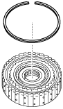
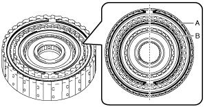
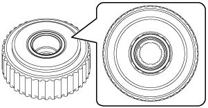
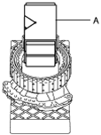
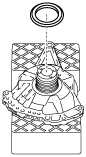
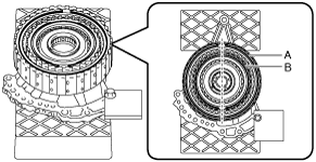
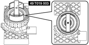
1. Assemble the snap ring to the position shown in the figure.
-
Caution
-
• Assemble so that the end gap of the snap ring is positioned diagonally opposed to the end gap of the snap ring for the high clutch.
• After assembling the snap ring, verify that the snap ring is securely inserted into the bottom of the snap ring groove.
-
Note
-
• Snap ring size: Outer diameter approx. 169.3 mm {6.665 in}
A :Snap ring (low clutch)
B :Snap ring (high clutch)
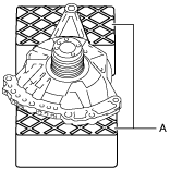
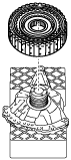
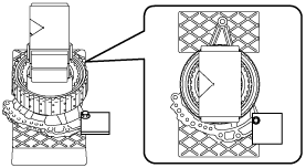
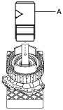
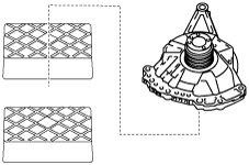
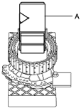
2. Set the oil pump on the workbench as shown in the figure.
-
Caution
-
• To reduce error during the low clutch clearance measurement, use the rubber plates to adjust the alignment surface of the oil pump with the transaxle case so that it is level.
A :Rubber plate
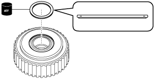
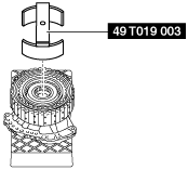
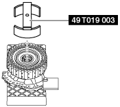
3. Assemble the thrust needle bearing to the high clutch component and low clutch component using the following procedure:
-
Note
-
• Thrust needle bearing size: Outer diameter approx. 72.7 mm {2.86 in}
- (1) To prevent the thrust needle bearing from dropping out, apply ATF (ATF FZ) to the thrust needle bearing.
-
- (2) Assemble the thrust needle bearing.
-
4. Assemble the parts assembled together in Step 3 to the oil pump.
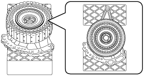
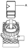
5. Install the SST.
6. Place a 98—196 N {10.0—19.9 kgf, 23.0—44.0 lbf} weight on the SST using the following procedure:
-
Note
-
• Use a V-block as a weight.
- (1) Measure the weight of the weight placed on the SST.
-
- (2) Input the measured weight into the measurement/adjustment value input sheet.
-
- (3) Place the measured weight on the SST.
-
-
Caution
-
• To reduce error during the low clutch clearance measurement, place the weight near the center of the SST.
A :Weight (V-block)
7. Perform the following calculation to calculate the correction value for the low clutch clearance.
-
Note
-
• Because a wave spring is included in the low clutch, a correction value is required for the low clutch clearance according to the weight of the weight used during the low clutch clearance measurement.
-
Correction value of low clutch clearance (weight of unit is N) = (A - 98 N) × 0.00157 mm {0.0000618 in}
-
A: Weight of weight
-
Note
-
Example
A: Weight of weight is 150 N
Correction value of low clutch clearance = (150 N - 98 N) × 0.00157 mm {0.0000618 in}= 0.0816 mm {0.00321 in}
-
Correction value of low clutch clearance (weight of unit is kgf) = (A - 9.99 kgf) × 0.01537 mm {0.0006051 in}
-
A: Weight of weight
-
Note
-
Example
A: Weight of weight is 15.30 kgf
Correction value of low clutch clearance = (15.30 kgf - 9.99 kgf) × 0.01537 mm {0.0006051 in}= 0.0816 mm {0.00321 in}
-
Correction value of low clutch clearance (weight of unit is lbf) = (A - 22.03 lbf) × 0.00698 mm {0.0002748 in}
-
A: Weight of weight
-
Note
-
Example
A: Weight of weight is 33.72 lbf
Correction value of low clutch clearance = (33.72 lbf - 22.03 lbf) × 0.00698 mm {0.0002748 in}= 0.0816 mm {0.00321 in}
8. Input the calculated correction value of the low clutch clearance into the measurement/adjustment value input sheet.
9. Set the measuring instrument to the oil pump using the following procedure:
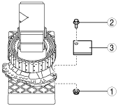
- (1) Install an appropriate steel plate for securing the magnetic stand used in the procedure shown in the figure.
-
-
Caution
-
• If the bolt and nut are tightened with excessive force when installing the steel plate, the alignment surface of the oil pump with the transaxle case could be damaged. Tighten the bolt and nut so that the steel plate does not move during low clutch clearance measurement.
-
Note
-
• When installing the steel plate to the oil pump, use an M8 bolt and nut.
|
1
|
Steel plate (for securing magnetic stand)
|
|
2
|
Bolt (M8)
|
|
3
|
Nut (M8)
|
-
Steel plate installation bolt tightening torque
-
15 N·m {1.5 kgf·m, 11 ft·lbf} or less (tighten so that steel plate does not move during low clutch clearance measurement)
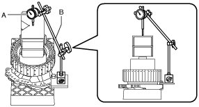
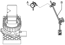
- (2) Set the dial gauge and magnetic stand as shown in the figure.
-
-
Caution
-
• To reduce error during the low clutch clearance measurement, set the dial gauge so that it is perpendicular to the alignment surface of the oil pump with the transaxle case.
A :Dial gauge
B :Magnetic stand
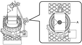
- (3) Set the dial gauge end near the center of the weight.
-
-
Caution
-
• To reduce error during the low clutch clearance measurement, set the dial gauge end to within the area shown in the figure.
A :Area in which dial gauge end is set
10. Measure the low clutch clearance using the following procedure:
- (1) Blow compressed air into the oil passage shown in the figure and verify the operation condition of the low clutch piston (approx. 3 times).
-
-
Warning
-
• Always wear protective eye wear when using the air compressor. Otherwise, ATF or dirt particles blown off by the air compressor could get into the eyes.
-
Caution
-
• To prevent damage to parts, always use an air compressor which is adjusted to the indicated pressure.
-
Compressed air pressure
-
0.39—0.44 MPa {4.0—4.4 kgf/cm2, 57—63 psi}
- (2) Blow compressed air into the oil passage shown in the figure and operate the low clutch piston to read the value when the dial gauge is stabilized.
-
-
Warning
-
• Always wear protective eye wear when using the air compressor. Otherwise, ATF or dirt particles blown off by the air compressor could get into the eyes.
-
Caution
-
• To prevent damage to parts, always use an air compressor which is adjusted to the indicated pressure.
-
Compressed air pressure
-
0.39—0.44 MPa {4.0—4.4 kgf/cm2, 57—63 psi}
- (3) Input the dial gauge value, which was read while the low clutch piston was operating, into the measurement/adjustment value input sheet.
-
- (4) Release the compressed air and read the dial gauge value without the low clutch piston operating.
-
- (5) Input the dial gauge value, which was read without the low clutch piston operating, into the measurement/adjustment value input sheet.
-
- (6) Perform the following calculation to calculate the low clutch clearance.
-
-
Low clutch clearance = C - D - B
-
B: Correction value of low clutch clearance
C: Dial gauge value with low clutch piston operated
D: Dial gauge value without low clutch piston operated
-
Note
-
Example
B: Correction value of low clutch clearance is 0.0816 mm {0.00321 in}
C: Dial gauge value with low clutch piston operated is 2.320 mm {0.09134 in}
D: Dial gauge value without low clutch piston operated is 0.595 mm {0.02343 in}
Low clutch clearance = 2.320 mm {0.09134 in} - 0.595 mm {0.02343 in} - 0.0816 mm {0.00321 in}= 1.6434 mm {0.064701 in}
- (7) Input the calculated low clutch clearance into the measurement/adjustment value input sheet.
-
- (8) Verify that the low clutch clearance satisfies the specification.
-
-
Specification
-
1.400—1.600 mm {0.05512—0.06299 in}
-
11. Remove the dial gauge and magnetic stand.
A :Dial gauge
B :Magnetic stand
12. Remove the steel plate for securing the magnetic stand using the procedure shown in the figure.
|
1
|
Nut (M8)
|
|
2
|
Bolt (M8)
|
|
3
|
Steel plate (for securing magnetic stand)
|
13. Remove the weight on the SST.
A :Weight (V-block)
14. Remove the SST.
15. Remove the high clutch component and low clutch component.
16. Remove the thrust needle bearing.
17. Take the oil pump off the rubber plates.
Low Clutch Clearance Adjustment
1. Remove the dial gauge and magnetic stand.
A :Dial gauge
B :Magnetic stand
2. Remove the weight on the SST.
A :Weight (V-block)
3. Remove the SST.
4. Remove the snap ring.
5. Measure the thickness of the removed snap ring.
-
Note
-
• Recommended measuring instrument: Micrometer
6. Input the measured snap ring thickness into the measurement/adjustment value input sheet.
7. Select the appropriate snap ring from the following table:
|
Range*
|
Selected snap ring thickness
|
|
Exceeds 3.650 mm {0.14370 in}, 3.750 mm {0.14764 in} or less
|
2.2 mm {0.087 in}
|
|
Exceeds 3.550 mm {0.13976 in}, 3.650 mm {0.14370 in} or less
|
2.1 mm {0.083 in}
|
|
Exceeds 3.450 mm {0.13583 in}, 3.550 mm {0.13976 in} or less
|
2.0 mm {0.079 in}
|
|
Exceeds 3.350 mm {0.13189 in}, 3.450 mm {0.13583 in} or less
|
1.9 mm {0.075 in}
|
|
Exceeds 3.250 mm {0.12795 in}, 3.350 mm {0.13189 in} or less
|
1.8 mm {0.071 in}
|
|
Exceeds 3.150 mm {0.12402 in}, 3.250 mm {0.12795 in} or less
|
1.7 mm {0.067 in}
|
|
Exceeds 3.050 mm {0.12008 in}, 3.150 mm {0.12402 in} or less
|
1.6 mm {0.063 in}
|
|
Exceeds 2.950 mm {0.11614 in}, 3.050 mm {0.12008 in} or less
|
1.5 mm {0.059 in}
|
|
Exceeds 2.850 mm {0.11220 in}, 2.950 mm {0.11614 in} or less
|
1.4 mm {0.055 in}
|
|
Exceeds 2.750 mm {0.10827 in}, 2.850 mm {0.11220 in} or less
|
1.3 mm {0.051 in}
|
|
Exceeds 2.650 mm {0.10433 in}, 2.750 mm {0.10827 in} or less
|
1.2 mm {0.047 in}
|
* :The range is the sum of the low clutch clearance and the thickness value of the removed snap ring.
-
Range = E + H
-
E: Low clutch clearance
H: Thickness of removed snap ring
-
Note
-
Example
E: Low clutch clearance is 1.6434 mm {0.064701 in}
H: Thickness of removed snap ring is 1.705 mm {0.06713 in}
Range = 1.6434 mm {0.064701 in}+ 1.705 mm {0.06713 in}= 3.3484 mm {0.13183 in}, the selected snap ring has a thickness of 1.8 mm {0.071 in}.
8. Assemble the selected snap ring to the position shown in the figure.
-
Caution
-
• Assemble so that the end gap of the snap ring is positioned diagonally opposed to the end gap of the snap ring for the high clutch.
• After assembling the snap ring, verify that the snap ring is securely inserted into the bottom of the snap ring groove.
-
Note
-
• Snap ring size: Outer diameter approx. 169.3 mm {6.665 in}
A :Snap ring (low clutch)
B :Snap ring (high clutch)
9. Install the SST.
10. Place a 98—196 N {10.0—19.9 kgf, 23.0—44.0 lbf} weight on the SST using the following procedure:
-
Note
-
• Use a V-block as a weight.
- (1) Measure the weight of the weight placed on the SST.
-
- (2) Input the measured weight into the measurement/adjustment value input sheet.
-
- (3) Place the measured weight on the SST.
-
-
Caution
-
• To reduce error during the low clutch clearance measurement, place the weight near the center of the SST.
A :Weight (V-block)
11. Perform the following calculation to calculate the correction value for the low clutch clearance.
-
Note
-
• Because a wave spring is included in the low clutch, a correction value is required for the low clutch clearance according to the weight of the weight used during the low clutch clearance measurement.
-
Correction value of low clutch clearance (weight of unit is N) = (A - 98 N) × 0.00157 mm {0.0000618 in}
-
A: Weight of weight
-
Note
-
Example
A: Weight of weight is 150 N
Correction value of low clutch clearance = (150 N - 98 N) × 0.00157 mm {0.0000618 in}= 0.0816 mm {0.00321 in}
-
Correction value of low clutch clearance (weight of unit is kgf) = (A - 9.99 kgf) × 0.01537 mm {0.0006051 in}
-
A: Weight of weight
-
Note
-
Example
A: Weight of weight is 15.30 kgf
Correction value of low clutch clearance = (15.30 kgf - 9.99 kgf) × 0.01537 mm {0.0006051 in}= 0.0816 mm {0.00321 in}
-
Correction value of low clutch clearance (weight of unit is lbf) = (A - 22.03 lbf) × 0.00698 mm {0.0002748 in}
-
A: Weight of weight
-
Note
-
Example
A: Weight of weight is 33.72 lbf
Correction value of low clutch clearance = (33.72 lbf - 22.03 lbf) × 0.00698 mm {0.0002748 in}= 0.0816 mm {0.00321 in}
12. Perform the low clutch clearance measurement from Step 9 (2). (See Low Clutch Clearance Measurement.)