 |
bgw2za00000124
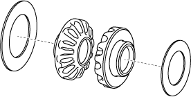
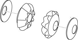
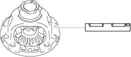
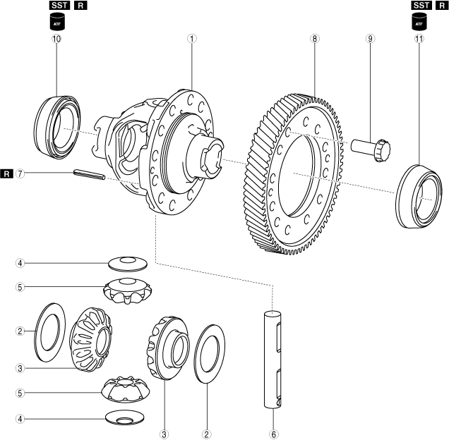
RING GEAR AND DIFFERENTIAL ASSEMBLY
id051700664100
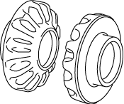
Structural View
bgw2za00000124
|
|
1
|
Differential gear case
|
|
2
|
Thrust washer (selection)
|
|
3
|
Side gear
|
|
4
|
Thrust washer
|
|
5
|
Pinion gear
|
|
6
|
Pinion shaft
|
|
7
|
Roll pin
|
|
8
|
Ring gear
|
|
9
|
12 bolts (M13×1.0 bolt, length approx. 26.2 mm {1.03 in})
|
|
10
|
Tapered roller bearing (converter housing side)
(inner diameter approx. 55 mm {2.2 in}, inner race width approx. 23 mm {0.91 in})
|
|
11
|
Tapered roller bearing (transaxle case side)
(inner diameter approx. 55 mm {2.2 in}, inner race width approx. 20 mm {0.79 in})
|
Assembly Procedure
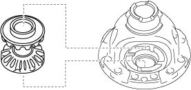
1. Assemble the thrust washers to the side gears.
azzjjw00001535
|
azzjjw00001536
|
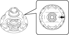
2. Assemble the side gears which have the thrust washers assembled to them.
bgw3ja00000477
|
bgw3ja00000478
|
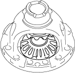
3. Assemble the thrust washers to the pinion gears.
azzjjw00001539
|
azzjjw00001540
|
4. Assemble the pinion gears which have the thrust washers assembled to them using the following procedure:
bgw3ja00000479
|
bgw3ja00000480
|
bgw3ja00000481
|
5. Assemble the pinion shaft.
bgw3ja00000482
|
bgw3ja00000483
|
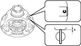
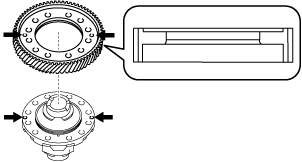
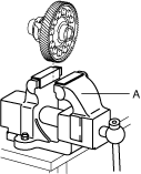
6. Assemble a new roll pin to the position shown in the figure using a pin punch.
bgw2za00000127
|
bgw3ja00000485
|
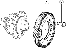
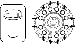
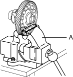
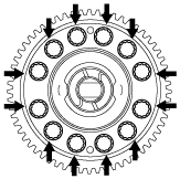
7. Assemble the ring gear using the following procedure:
bgw3ja00000486
|
|
1
|
Ring gear
|
|
2
|
12 bolts (M13×1.0 bolt, length approx. 26.2 mm {1.03 in})
|
bgw3ja00000487
|
bgw3ja00000488
|
bgw3ja00000489
|
bgw3ja00000490
|
bgw3ja00000491
|
bgw3ja00000492
|
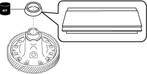
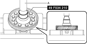
8. Assemble the tapered roller bearing (converter housing side) using the following procedure:
bgw2za00000128
|
bgw2za00000129
|
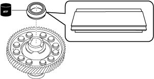
9. Assemble the tapered roller bearing (transaxle case side) using the following procedure:
bgw2za00000130
|
bgw2za00000131
|
10. Perform the differential backlash measurement/adjustment. (See DIFFERENTIAL BACKLASH MEASUREMENT/ADJUSTMENT.)