 |
bd62zm00000018
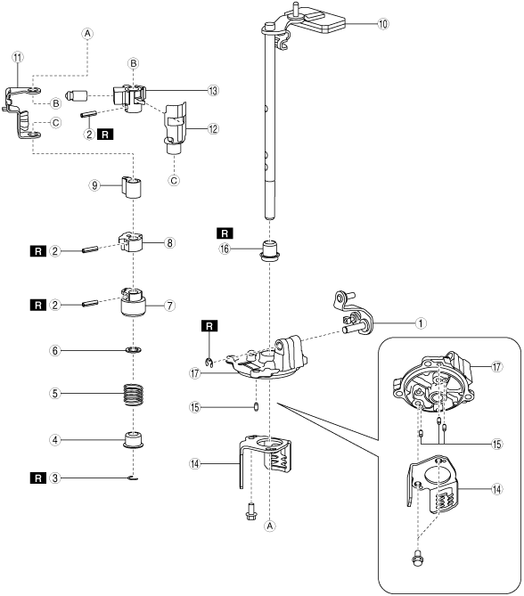
SHIFT CONTROL MODULE DISASSEMBLY
id051500175400
1. Disassemble the shift control module in the order shown in the figure.
bd62zm00000018
|
|
1
|
Select lever
|
|
2
|
Pin
(See Pin Removal Note.)
|
|
3
|
Clip
(See Clip Removal Note.)
|
|
4
|
Spring seat
|
|
5
|
Spring
|
|
6
|
Washer
|
|
7
|
Control lever No.1
|
|
8
|
Switch pin No.1
|
|
9
|
Switch pin No.2
|
|
10
|
Shift lever
|
|
11
|
Plate
|
|
12
|
Interlock sleeve
|
|
13
|
Control lever No.2 component
|
|
14
|
Guide plate
|
|
15
|
Dowel pin
|
|
16
|
Oil seal
|
|
17
|
Control case
|
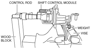
Pin Removal Note
1. Secure the weight part of the shift lever using a vice, and support the control rod part using a woodblock as shown in the figure.
bd62zm00000019
|
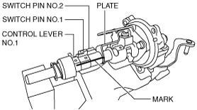
2. Mark the control lever No.1, switch pin No.1, switch pin No.2 and holder plate as shown in the figure.
bd62zm00000020
|
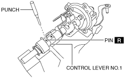
3. Remove the pin from the control lever No.1 using a punch.
bd62zm00000021
|
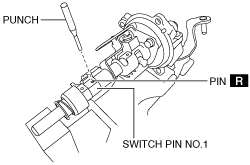
4. Remove the pin from the switch pin No.1 using a punch.
bd62zm00000022
|
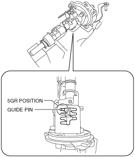
5. Move the shift lever to set the guide pin to the 5GR position of the guide plate.
bd62zm00000023
|
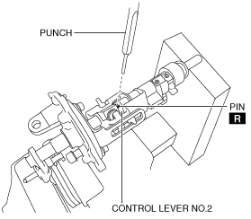
6. Remove the pin from the control lever No.2 using a punch.
bd62zm00000024
|
Clip Removal Note
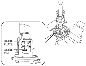
1. Move the guide pin to the position shown in the figure for the guide plate.
bd62zm00000025
|
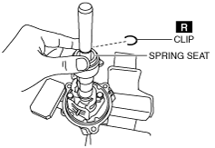
2. Push down the spring seat by hand.
bd62zm00000026
|
3. Detach the clip.