 |
bd62zm00000027
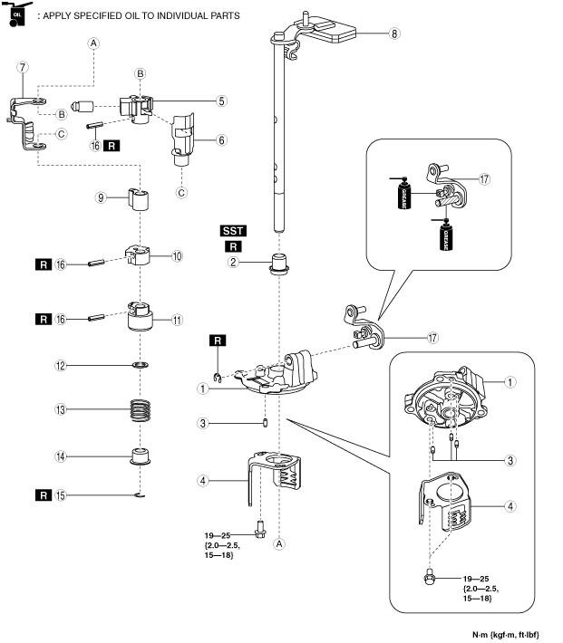
SHIFT CONTROL MODULE ASSEMBLY
id051500175500
1. Assemble the shift control module using the procedure shown in the figure.
bd62zm00000027
|
|
1
|
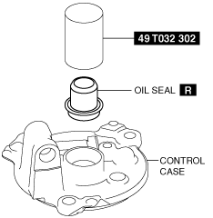
Control case
|
|
2
|
Oil seal
(See Oil Seal Assembly Note.)
|
|
3
|
Dowel pin
|
|
4
|
Guide plate
|
|
5
|
Control lever No.2 component
|
|
6
|
Interlock sleeve
|
|
7
|
Plate
|
|
8
|
Shift lever
|
|
9
|
Switch pin No.2
|
|
10
|
Switch pin No.1
|
|
11
|
Control lever No.1
|
|
12
|
Washer
|
|
13
|
Spring
|
|
14
|
Spring seat
|
|
15
|
Clip
(See Clip Assembly Note.)
|
|
16
|
Pin
(See Pin Assembly Note.)
|
|
17
|
Selector lever
|
Oil Seal Assembly Note
1. Assemble a new oil seal to the control case using the SST.
bd62zm00000028
|
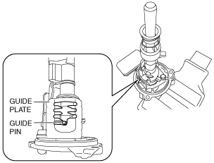
Clip Assembly Note
1. Move the guide pin to the position shown in the figure for the guide plate.
bd62zm00000029
|
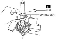
2. Push down the spring seat by hand.
bd62zm00000030
|
3. Assemble the clip.
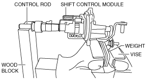
Pin Assembly Note
1. Secure the weight part of the shift lever using a vice, and support the control rod part using a woodblock as shown in the figure.
bd62zm00000031
|
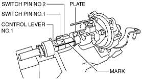
2. Align the control lever No.1, switch pin No.1, switch pin No.2 and holder plate markings.
bd62zm00000032
|
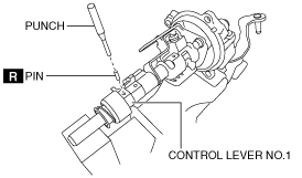
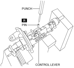
3. Assemble a new pin to the control lever No.1 using a punch.
bd62zm00000033
|
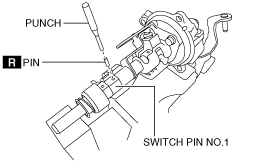
4. Assemble a new pin to the switch pin No.1 using a punch.
bd62zm00000034
|
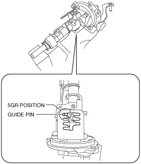
5. Move the control lever component to set the guide pin to the 5GR position of the guide plate.
bd62zm00000035
|
6. Assemble a new pin to the control lever No.2 using a punch.
bd62zm00000036
|