BEARING PRELOAD ADJUSTMENT
id051500177100
Primary Shaft Preload Adjustment
1. Measure the thickness of the straight edge which is used for measurements.
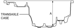
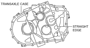
2. Measure distance A of the transaxle case using the following procedure:
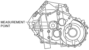
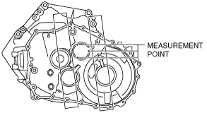
- (1) After the bolt and nut are assembled to the positions shown in the figure, secure the bolt with a vise to secure the transaxle case.
-
-
Bolt
-
Part No.: 99450 0855 or M8×1.25 length 55 mm {2.2 in}
-
Nut
-
M8×1.25
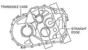
- (2) Place two straight edges on the transaxle case as shown in the figure.
-
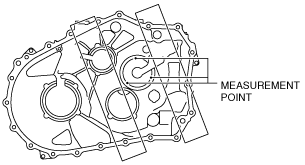
- (3) Set up 3 measurement points of your choosing on the shim assembly area of the transaxle case as shown in the figure.
-
- (4) Using a commercially available depth gauge, measure the distance to each measurement point from the straight edge.
-
-
Caution
-
• When measuring the distance to the measurement point from the straight edge, do not allow the depth gauge head to contact the shim assembly area.
- (5) Calculate the average value measured in Step 3 using the following formula.
-
-
• (Value of first measurement + value of second measurement + value of third measurement) / 3 = Average measured values.
-
Calculation example
-
• Value of first measurement =212.500 mm {8.36615 in}
• Value of second measurement =212.506 mm {8.36638 in}
• Value of third measurement =212.510 mm {8.36654 in}
• (212.500 mm {8.36615 in}+212.506 mm {8.36638 in}+212.510 mm {8.36654 in}) / 3 =212.505 mm {8.36634 in}
- (6) Calculate distance A of the transaxle case using the following formula.
-
-
• Average of measured values - straight edge thickness = Distance A
-
Calculation example
-
• Straight edge thickness =5.000 mm {0.1969 in}
• Average of measured values =212.505 mm {8.36634 in}
• 212.505 mm {8.36634 in} - 5.000 mm {0.1969 in}=207.505 mm {8.16949 in}
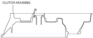
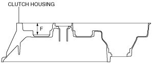
3. Measure distance B of the clutch housing using the following procedure:
- (1) Set two straight edges on the clutch housing as shown in the figure.
-
- (2) Set up 3 measurement points of your choosing on the ball bearing assembly area of the clutch housing as shown in the figure.
-
- (3) Using a commercially available depth gauge, measure the distance to each measurement point from the straight edge.
-
-
Caution
-
• When measuring the distance to the measurement points from the straight edge, do not allow the depth gauge head to contact the ball bearing assembly area.
- (4) Calculate the average value measured in Step 3 using the following formula.
-
-
• (Value of first measurement + value of second measurement + value of third measurement) / 3 = Average measured values.
-
Calculation example
-
• Value of first measurement =18.551 mm {0.73035 in}
• Value of second measurement =18.550 mm {0.73032 in}
• Value of third measurement =18.552 mm {0.73039 in}
• (18.551 mm {0.73035 in}+18.550 mm {0.73032 in}+18.552 mm {0.73039 in}) / 3 =18.551 mm {0.73035 in}
- (5) Calculate distance B of the clutch housing using the following formula.
-
-
• Average of measured values - straight edge thickness = Distance B
-
Calculation example
-
• Straight edge thickness =5.000 mm {0.1969 in}
• Average of measured values =18.551 mm {0.73035 in}
• 18.551 mm {0.73035 in} - 5.000 mm {0.1969 in}=13.551 mm {0.53350 in}
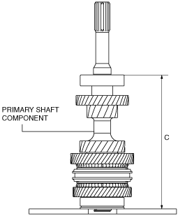
4. Measure distance C of the primary shaft component using the following procedure:
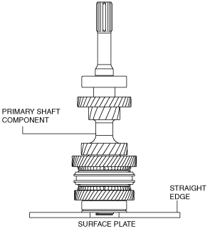
- (1) Place two straight edges on the surface plate as shown in the figure and set the primary shaft component on top of them.
-
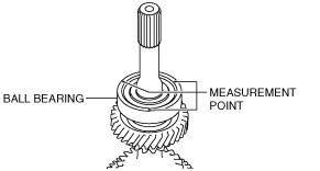
- (2) Set up 3 measurement points of your choosing on the ball bearing as shown in the figure.
-
- (3) Using a commercially available height gauge, measure the distance to each measurement point from the straight edge.
- (4) Calculate the average of the value measured in Step 3 using the following formula, and use the average of the measured value for distance C of the primary shaft component.
-
-
• (Value of first measurement + value of second measurement + value of third measurement) / 3 = Distance C
-
Calculation example
-
• Value of first measurement =220.234 mm {8.67063 in}
• Value of second measurement =220.235 mm {8.67067 in}
• Value of third measurement =220.236 mm {8.67071 in}
• (220.234 mm {8.67063 in}+220.235 mm {8.67067 in}+220.236 mm {8.67071 in}) / 3 =220.235 mm {8.67067 in}
5. Select the primary shaft shim using the following procedure:
- (1) Calculate the clearance (clearance D) between the transaxle case and the primary shaft component using the following formula.
-
-
• Distance A + Distance B - Distance C = Clearance D
-
Calculation example
-
• Distance A =207.505 mm {8.16949 in}
• Distance B =13.551 mm {0.53350 in}
• Distance C =220.235 mm {8.67067 in}
• 207.505 mm {8.16949 in}+13.551 mm {0.53350 in} - 220.235 mm {8.67067 in}=0.821 mm {0.0323 in}
- (2) Based on the calculated clearance D, select a shim of the appropriate thickness from the following table.
- However, there are two types of the transaxle cases. Refer to the “Method for determining transaxle case Type A/Type B” and select the shim from the corresponding table. (See Method for determining transaxle case Type A/Type B)
Transaxle case Type A
|
Clearance D measured value
|
Appropriate shim thickness (mm {in})
|
|
Equal to or more (mm {in})
|
Less than (mm {in})
|
|
1.225 {0.04823}
|
1.275 {0.05020}
|
1.050 {0.04134}
|
|
1.175 {0.04626}
|
1.225 {0.04823}
|
1.000 {0.03937}
|
|
1.125 {0.04429}
|
1.175 {0.04626}
|
0.950 {0.0374}
|
|
1.075 {0.04232}
|
1.125 {0.04429}
|
0.900 {0.0354}
|
|
1.025 {0.04035}
|
1.075 {0.04232}
|
0.850 {0.0335}
|
|
0.975 {0.0384}
|
1.025 {0.04035}
|
0.800 {0.0315}
|
|
0.925 {0.0364}
|
0.975 {0.0384}
|
0.750 {0.0295}
|
|
0.875 {0.0344}
|
0.925 {0.0364}
|
0.700 {0.0276}
|
|
0.825 {0.0325}
|
0.875 {0.0344}
|
0.650 {0.0256}
|
|
0.775 {0.0305}
|
0.825 {0.0325}
|
0.600 {0.0236}
|
|
0.725 {0.0285}
|
0.775 {0.0305}
|
0.550 {0.0217}
|
|
0.675 {0.0266}
|
0.725 {0.0285}
|
0.500 {0.0197}
|
|
0.625 {0.0246}
|
0.675 {0.0266}
|
0.450 {0.0177}
|
|
0.575 {0.0226}
|
0.625 {0.0246}
|
0.400 {0.0157}
|
|
0.525 {0.0207}
|
0.575 {0.0226}
|
0.350 {0.0138}
|
|
0.475 {0.0187}
|
0.525 {0.0207}
|
0.300 {0.0118}
|
Transaxle case Type B
|
Clearance D measured value
|
Appropriate shim thickness (mm {in})
|
|
Equal to or more (mm {in})
|
Less than (mm {in})
|
|
1.150 {0.04528}
|
1.200 {0.04724}
|
1.050 {0.04134}
|
|
1.100 {0.04331}
|
1.150 {0.04528}
|
1.000 {0.03937}
|
|
1.050 {0.04134}
|
1.100 {0.04331}
|
0.950 {0.0374}
|
|
1.000 {0.03937}
|
1.050 {0.04134}
|
0.900 {0.0354}
|
|
0.950 {0.0374}
|
1.000 {0.03937}
|
0.850 {0.0335}
|
|
0.900 {0.0354}
|
0.950 {0.0374}
|
0.800 {0.0315}
|
|
0.850 {0.0335}
|
0.900 {0.0354}
|
0.750 {0.0295}
|
|
0.800 {0.0315}
|
0.850 {0.0335}
|
0.700 {0.0276}
|
|
0.750 {0.0295}
|
0.800 {0.0315}
|
0.650 {0.0256}
|
|
0.700 {0.0276}
|
0.750 {0.0295}
|
0.600 {0.0236}
|
|
0.650 {0.0256}
|
0.700 {0.0276}
|
0.550 {0.0217}
|
|
0.600 {0.0236}
|
0.650 {0.0256}
|
0.500 {0.0197}
|
|
0.550 {0.0217}
|
0.600 {0.0236}
|
0.450 {0.0177}
|
|
0.50 {0.0197}
|
0.550 {0.0217}
|
0.400 {0.0157}
|
|
0.450 {0.0177}
|
0.50 {0.0197}
|
0.350 {0.0138}
|
|
0.40 {0.0157}
|
0.450 {0.0177}
|
0.300 {0.0118}
|
-
Selection example
-
• Transaxle case Type A
Because clearance D 0.821 mm {0.0323 in} applies to 0.775 {0.0305} or more and less than 0.825 {0.0325}, a shim of 0.600 {0.0236} thickness is selected.
• Transaxle case Type B
Because clearance D 0.821 mm {0.0323 in} applies to 0.800 {0.0315} or more and less than 0.850 {0.0335}, a shim of 0.700 {0.0276} thickness is selected.
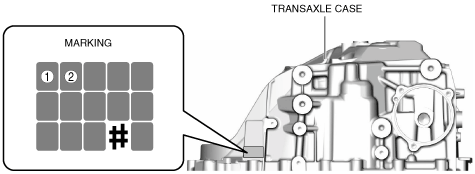
Method for determining transaxle case Type A/Type B
Determine the method for determining the transaxle cases Type A/Type B using the marking on the transaxle case and the number of the corresponding table.
1. Verify the markings of (1) and (2) shown in the figure for the transaxle case.
2. Change the markings of (1) and (2) to each number using the following table.
Corresponding table for marking and number
|
Marking
|
0
|
1
|
2
|
3
|
4
|
5
|
6
|
7
|
8
|
9
|
|
Number
|
0
|
1
|
2
|
3
|
4
|
5
|
6
|
7
|
8
|
9
|
|
Marking
|
A
|
B
|
C
|
D
|
E
|
F
|
G
|
H
|
I
|
J
|
|
Number
|
10
|
11
|
12
|
13
|
14
|
15
|
16
|
17
|
18
|
19
|
|
Marking
|
K
|
L
|
M
|
N
|
O
|
P
|
Q
|
R
|
S
|
T
|
|
Number
|
20
|
21
|
22
|
23
|
24
|
25
|
26
|
27
|
28
|
29
|
|
Marking
|
U
|
V
|
W
|
X
|
Y
|
Z
|
—
|
—
|
—
|
—
|
|
Number
|
30
|
31
|
32
|
33
|
34
|
35
|
—
|
—
|
—
|
—
|
3. Determine transaxle cases Type A/Type B from the following table.
|
Numbers of (1) and (2)
|
Transaxle case type
|
|
The number in (1) is 13 or less
|
Type A
|
|
The number in (1) is 14 and the number in (2) is 11 or less
|
Type A
|
|
The number in (1) is 14 and the number in (2) is 12 or more
|
Type B
|
|
The number in (1) is 15 or more
|
Type B
|
Secondary Shaft No.2 Preload Adjustment
1. Measure the thickness of the straight edge which is used for measurements.
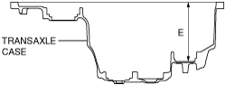
2. Measure distance E of the transaxle case using the following procedure:
- (1) After the bolt and nut are assembled to the positions shown in the figure, secure the bolt with a vise to secure the transaxle case.
-
-
Bolt
-
Part No.: 99450 0855 or M8×1.25 length 55 mm {2.2 in}
-
Nut
-
M8×1.25
- (2) Place two straight edges on the transaxle case as shown in the figure.
-
- (3) Set up 3 measurement points of your choosing on the shim assembly area of the transaxle case as shown in the figure.
-
- (4) Using a commercially available depth gauge, measure the distance to each measurement point from the straight edge.
-
-
Caution
-
• When measuring the distance to the measurement point from the straight edge, do not allow the depth gauge head to contact the shim assembly area.
- (5) Calculate the average value measured in Step 3 using the following formula.
-
-
• (Value of first measurement + value of second measurement + value of third measurement) / 3 = Average measured values.
-
Calculation example
-
• Value of first measurement =157.403 mm {6.19697 in}
• Value of second measurement =157.401 mm {6.19689 in}
• Value of third measurement =157.402 mm {6.19693 in}
• (157.403 mm {6.19697 in}+157.401 mm {6.19689 in}+157.402 mm {6.19693 in}) / 3 =157.402 mm {6.19693 in}
- (6) Calculate distance E of the transaxle case using the following formula.
-
-
• Average of measured values - straight edge thickness = Distance E
-
Calculation example
-
• Straight edge thickness =5.000 mm {0.1969 in}
• Average of measured values =157.402 mm {6.19693 in}
• 157.402 mm {6.19693 in} - 5.000 mm {0.1969 in}=152.402 mm {6.00008 in}
3. Measure distance F of the clutch housing using the following procedure:
- (1) Set two straight edges on the clutch housing as shown in the figure.
-
- (2) Set up 3 measurement points of your choosing on the ball bearing assembly area of the clutch housing as shown in the figure.
-
- (3) Using a commercially available depth gauge, measure the distance to each measurement point from the straight edge.
-
-
Caution
-
• When measuring the distance to the measurement point from the straight edge, do not allow the depth gauge head to contact the bearing outer race assembly area.
- (4) Calculate the average value measured in Step 3 using the following formula.
-
-
• (Value of first measurement + value of second measurement + value of third measurement) / 3 = Average measured values.
-
Calculation example
-
• Value of first measurement =56.269 mm {2.2153 in}
• Value of second measurement =56.268 mm {2.2153 in}
• Value of third measurement =56.267 mm {2.2152 in}
• (56.269 mm {2.2153 in}+56.268 mm {2.2153 in}+56.267 mm {2.2152 in}) / 3 =56.268 mm {2.2153 in}
- (5) Calculate distance F of the clutch housing using the following formula.
-
-
• Average of measured values - straight edge thickness = Distance F
-
Calculation example
-
• Straight edge thickness =5.000 mm {0.1969 in}
• Average of measured values =56.268 mm {2.2153 in}
• 56.268 mm {2.2153 in} - 5.000 mm {0.1969 in}=51.268 mm {2.0184 in}
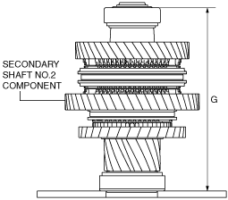
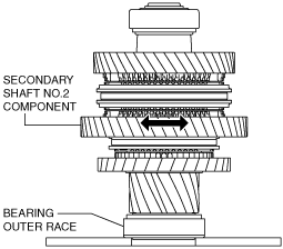
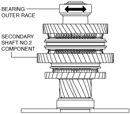
4. Measure distance G of the secondary shaft component using the following procedure:
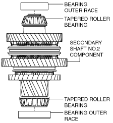
- (1) Assemble the bearing outer race to the tapered roller bearing for the secondary shaft No.2 component.
-
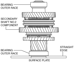
- (2) Place two straight edges on the surface plate as shown in the figure and set the bearing outer race and secondary shaft component on top of them.
-
- (3) Rotate the secondary shaft No.2 component to engage the tapered roller bearing with the bearing outer race on the clutch housing side.
-
- (4) Rotate the bearing outer race on the transaxle case side to engage the tapered roller bearing with the bearing outer race.
-
- (5) Set up 3 measurement points of your choosing on the bearing outer race as shown in the figure.
-
- (6) Using a commercially available height gauge, measure the distance to each measurement point from the straight edge.
- (7) Calculate the average of the value measured in Step 4 using the following formula, and use the average of the measured value for distance G of the secondary shaft component.
-
-
• (Value of first measurement + value of second measurement + value of third measurement) / 3 = Distance G
-
Calculation example
-
• Value of first measurement =202.819 mm {7.98500 in}
• Value of second measurement =202.818 mm {7.98496 in}
• Value of third measurement =202.820 mm {7.98504 in}
• (202.819 mm {7.98500 in}+202.818 mm {7.98496 in}+202.820 mm {7.98504 in}) / 3 =202.819 mm {7.98500 in}
5. Select the secondary shaft shim using the following procedure:
- (1) Calculate the clearance (clearance H) between the transaxle case and the primary shaft component using the following formula.
-
-
• Distance E + Distance F - Distance G = Clearance H
-
Calculation example
-
• Distance E =152.402 mm {6.00008 in}
• Distance F =51.268 mm {2.0184 in}
• Distance G =202.819 mm {7.98500 in}
• 152.402 mm {6.00008 in}+51.268 mm {2.0184 in} - 202.819 mm {7.98500 in}=0.851 mm {0.0335 in}
- (2) Based on the calculated clearance H, select a shim of the appropriate thickness from the following table.
-
|
Clearance H measured value
|
Appropriate shim thickness (mm {in})
|
|
Equal to or more (mm {in})
|
Less than (mm {in})
|
|
1.237 {0.04870}
|
1.287 {0.05067}
|
1.500 {0.05906}
|
|
1.187 {0.04673}
|
1.237 {0.04870}
|
1.450 {0.05709}
|
|
1.137 {0.04476}
|
1.187 {0.04673}
|
1.400 {0.05512}
|
|
1.087 {0.04280}
|
1.137 {0.04476}
|
1.350 {0.05315}
|
|
1.037 {0.04083}
|
1.087 {0.04280}
|
1.300 {0.05118}
|
|
0.987 {0.0389}
|
1.037 {0.04083}
|
1.250 {0.04921}
|
|
0.937 {0.0369}
|
0.987 {0.0389}
|
1.200 {0.04724}
|
|
0.887 {0.0349}
|
0.937 {0.0369}
|
1.150 {0.04528}
|
|
0.837 {0.0330}
|
0.887 {0.0349}
|
1.100 {0.04331}
|
|
0.787 {0.0310}
|
0.837 {0.0330}
|
1.050 {0.04134}
|
|
0.737 {0.0290}
|
0.787 {0.0310}
|
1.000 {0.03937}
|
|
0.687 {0.0270}
|
0.737 {0.0290}
|
0.950 {0.0374}
|
|
0.637 {0.0251}
|
0.687 {0.0270}
|
0.900 {0.0354}
|
|
0.587 {0.0231}
|
0.637 {0.0251}
|
0.850 {0.0335}
|
|
0.537 {0.0211}
|
0.587 {0.0231}
|
0.800 {0.0315}
|
|
0.487 {0.0192}
|
0.537 {0.0211}
|
0.750 {0.0295}
|
|
0.437 {0.0172}
|
0.487 {0.0192}
|
0.700 {0.0276}
|
|
0.387 {0.0152}
|
0.437 {0.0172}
|
0.650 {0.0256}
|
|
0.337 {0.0133}
|
0.387 {0.0152}
|
0.600 {0.0236}
|
Selection example
• Because clearance H 0.851 mm {0.0335 in} applies to 0.837 {0.0330} or more and less than 0.887 {0.0349}, a shim of 1.100 {0.04331} thickness is selected.
Differential Preload Adjustment
1. After the bolt and nut are assembled to the positions shown in the figure, secure the bolt with a vise to secure the transaxle case.
-
Bolt
-
Part No.: 99450 0855 or M8×1.25 length 55 mm {2.2 in}
-
Nut
-
M8×1.25
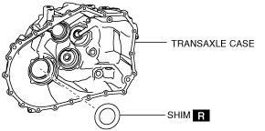
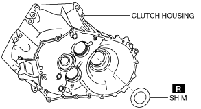
2. Assemble a new shim of the same thickness as the removed shim to the transaxle case.
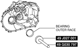
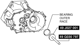
3. Assemble the bearing outer race to the transaxle case using the SSTs.
4. Assemble a new shim to the clutch housing.
5. Assemble the bearing outer race to the clutch housing using the SSTs.
6. Assemble the SST to the clutch housing.
-
Bolt A
-
Part No.: 99450 1055 or M10×1.25 length 55 mm {2.2 in}
-
Bolt A tightening torque
-
38—52 N·m {3.9—5.3 kgf·m, 29—38 ft·lbf}
-
Bolt B
-
SST (49 G019 003 part of 49 G019 0A0)
-
Bolt B tightening torque
-
88—118 N·m {9.0—12 kgf·m, 65—87 ft·lbf}
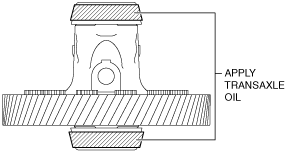
7. Apply transaxle oil to the roller area of the tapered roller bearing on the differential.
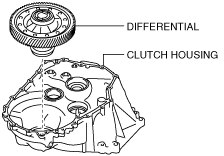
8. Assemble the differential to the clutch housing.
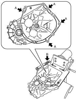
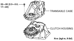
9. Assemble the transaxle case to the clutch housing.
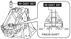
10. Set the SST so that its end engages the pinion shaft of the differential.
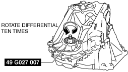
11. Rotate the differential ten times using the SST to engage the tapered roller bearing and the bearing outer race smoothly.
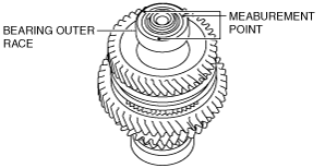
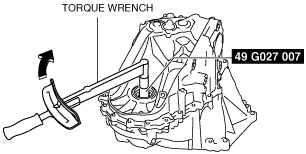
12. Rotate the differential once as shown in the figure taking approx. 6 s, and measure the differential preload.
-
Standard preload
-
2.7—3.9 N·m {28—39 kgf·cm, 24—34 in·lbf}
-
• If the measured preload is within the specification, the shim thickness is the same as the removed one and there is no problem, therefore the "Differential Preload Adjustment" procedure is finished.
Shim selection calculation
1. Calculate the preload gap by subtracting the measured preload value from constant number A.
-
• Constant number A =3.3 N·m {34 kgf·cm, 29 in·lbf}
• 3.3 N·m {34 kgf·cm, 29 in·lbf} - measured preload value = preload gap
Calculation example
-
• Measured preload value =4.6 N·m {47 kgf·cm, 41 in·lbf}
• 3.3 N·m {34 kgf·cm, 29 in·lbf} - 4.6 N·m {47 kgf·cm, 41 in·lbf}=-1.3 N·m {-13 kgf·cm, -12 in·lbf}
2. Calculate the shim thickness gap by multiplying the preload gap by constant number B.
-
Calculation method [N·m]
-
• Constant number B =0.071
• Preload gap x 0.071= shim thickness gap
Calculation example
-
• Preload gap =-1.3N·m
• -1.3N·m x 0.071 =–0.092 mm
-
Calculation method [kgf·cm]
-
• Constant number B =0.007
• Preload gap x 0.0071= shim thickness gap
Calculation example
-
• Preload gap =-13 kgf·cm
• -13 kgf·cm x 0.0071=–0.092 mm
-
Calculation method [in·lbf]
-
• Constant number B =0.0003
• Preload gap x 0.0003= shim thickness gap
Calculation example
-
• Preload gap =-12 in·lbf
• -12 in·lbf x 0.0003=-0.0036 in
3. Calculate the shim thickness calculated value by adding the shim thickness gap to the thickness of the shim used in the measurement.
-
• Shim thickness gap + thickness of shim used in measurement = shim thickness calculated value
Calculation example
-
• Shim thickness gap =–0.092 mm {–0.0036 in}
• Thickness of shim used in measurement =0.9000 mm {0.03543 in}
• –0.092 mm {–0.0036 in}+0.9000 mm {0.03543 in}=0.8077 mm {0.03180 in}
4. Based on the shim thickness calculated value, select a shim of the appropriate thickness.
|
Shim thickness calculated value
|
Appropriate shim thickness (mm {in})
|
|
Equal to or more (mm {in})
|
Less than (mm {in})
|
|
1.525 {0.06004}
|
1.575 {0.06201}
|
1.550 {0.06102}
|
|
1.475 {0.05807}
|
1.525 {0.06004}
|
1.500 {0.05906}
|
|
1.425 {0.05610}
|
1.475 {0.05807}
|
1.450 {0.05709}
|
|
1.375 {0.05413}
|
1.425 {0.05610}
|
1.400 {0.05512}
|
|
1.325 {0.05217}
|
1.375 {0.05413}
|
1.350 {0.05315}
|
|
1.275 {0.05020}
|
1.325 {0.05217}
|
1.300 {0.05118}
|
|
1.225 {0.04823}
|
1.275 {0.05020}
|
1.250 {0.04921}
|
|
1.175 {0.04626}
|
1.225 {0.04823}
|
1.200 {0.04724}
|
|
1.125 {0.04429}
|
1.175 {0.04626}
|
1.150 {0.04528}
|
|
1.075 {0.04232}
|
1.125 {0.04429}
|
1.100 {0.04331}
|
|
1.025 {0.04035}
|
1.075 {0.04232}
|
1.050 {0.04134}
|
|
0.975 {0.0384}
|
1.025 {0.04035}
|
1.000 {0.03937}
|
|
0.925 {0.0364}
|
0.975 {0.0384}
|
0.950 {0.0374}
|
|
0.875 {0.0344}
|
0.925 {0.0364}
|
0.900 {0.0354}
|
|
0.825 {0.0325}
|
0.875 {0.0344}
|
0.850 {0.0335}
|
|
0.775 {0.0305}
|
0.825 {0.0325}
|
0.800 {0.0315}
|
|
0.725 {0.0285}
|
0.775 {0.0305}
|
0.750 {0.0295}
|
|
0.675 {0.0266}
|
0.725 {0.0285}
|
0.700 {0.0276}
|
|
0.625 {0.0246}
|
0.675 {0.0266}
|
0.650 {0.0256}
|
|
0.575 {0.0226}
|
0.625 {0.0246}
|
0.600 {0.0236}
|
|
0.525 {0.0207}
|
0.575 {0.0226}
|
0.550 {0.0217}
|
-
Selection example
-
• Because shim thickness calculated value 0.8077 mm {0.03180 in}applies to 0.775 mm {0.0305 in} or more and less than 0.825 mm {0.0325 in}, a shim of 0.800 mm {0.0315 in} thickness is selected.
-
Note
-
• The preload gap is the difference between the central value of the standard preload value and the measured preload value.
• Constant number A, 3.3 N·m {34 kgf·cm, 29 in·lbf} is the central value of the standard preload value.
• The shim thickness gap is the difference between the thickness of the removed shim and the thickness of an appropriate shim. In the formula to calculate the shim thickness gap, the shim thickness gap is calculated by multiplying the preload gap with constant number B.
• Constant number B is the shim thickness which varies each time the preload changes by 1.0 N·m {10 kgf·cm, 8.9 in·lbf}. Because the shim thickness changes 0.1 mm {0.004 in} when the preload changes 1.4 N·m {14 kgf·cm, 12 in·lbf}, the quotient is 0.071 mm/N·m {0.0071 mm/kgf·cm 0.0003 in/in·lbf}.