|
1
|
RECORD FREEZE FRAME DATA/SNAPSHOT DATA AND DIAGNOSTIC MONITORING TEST RESULTS TO UTILIZE WITH REPEATABILITY VERIFICATION
-
Note
-
• Recording can be facilitated using the screen capture function of the PC.
• Record the FREEZE FRAME DATA/snapshot data and DIAGNOSTIC MONITORING TEST RESULTS (fuel system related) on the repair order.
|
—
|
Go to the next step.
|
|
2
|
VERIFY RELATED SERVICE INFORMATION AVAILABILITY
• Verify related Service Information availability.
• Is any related Service Information available?
|
Yes
|
Perform repair or diagnosis according to the available Service Information.
• If the vehicle is not repaired, go to the next step.
|
|
No
|
Go to the next step.
|
|
3
|
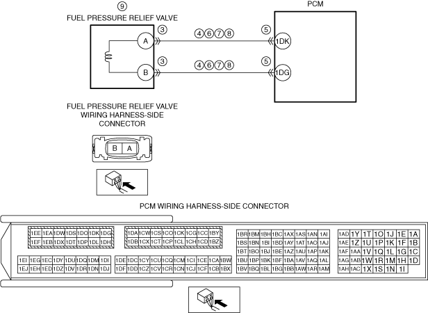
INSPECT FUEL PRESSURE RELIEF VALVE CONNECTOR CONDITION
• Switch the ignition off.
• Disconnect the fuel pressure relief valve connector.
• Inspect for poor connection (such as damaged/pulled-out pins, corrosion).
• Is there any malfunction?
|
Yes
|
Repair or replace the connector and/or terminals, then go to Step 10.
|
|
No
|
Go to the next step.
|
|
4
|
INSPECT FUEL PRESSURE RELIEF VALVE CIRCUIT FOR SHORT TO GROUND
• Verify that the fuel pressure relief valve connector is disconnected.
• Inspect for continuity between the following terminals (wiring harness-side) and body ground:
-
― Fuel pressure relief valve terminal A
― Fuel pressure relief valve terminal B
• Is there continuity?
|
Yes
|
If the short to ground circuit could be detected in the wiring harness:
• Refer to the wiring diagram and verify whether or not there is a common connector between the following terminals:
-
― Fuel pressure relief valve terminal A—PCM terminal 1DK
― Fuel pressure relief valve terminal B—PCM terminal 1DG
If there is a common connector:
-
― Determine the malfunctioning part by inspecting the common connector and the terminal for corrosion, damage, or pin disconnection, and the common wiring harness for a short to ground.
― Repair or replace the malfunctioning part.
If there is no common connector:
-
― Repair or replace the wiring harness which has a short to ground.
If the short to ground circuit could not be detected in the wiring harness:
• Replace the PCM (short to ground in the PCM internal circuit).
Go to Step 10.
|
|
No
|
Go to the next step.
|
|
5
|
INSPECT PCM CONNECTOR CONDITION
• Disconnect the PCM connector.
• Inspect for poor connection (such as damaged/pulled-out pins, corrosion).
• Is there any malfunction?
|
Yes
|
Repair or replace the connector and/or terminals, then go to Step 10.
|
|
No
|
Go to the next step.
|
|
6
|
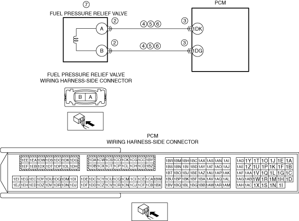
INSPECT FUEL PRESSURE RELIEF VALVE CIRCUIT FOR SHORT TO POWER SUPPLY
• Verify that the fuel pressure relief valve and PCM connectors are disconnected.
• Switch the ignition ON (engine off).
• Measure the voltage at the following terminals (wiring harness-side):
-
― Fuel pressure relief valve terminal A
― Fuel pressure relief valve terminal B
• Is the voltage 0 V?
|
Yes
|
Go to the next step.
|
|
No
|
Refer to the wiring diagram and verify whether or not there is a common connector between the following terminals:
• Fuel pressure relief valve terminal A—PCM terminal 1DK
• Fuel pressure relief valve terminal B—PCM terminal 1DG
If there is a common connector:
• Determine the malfunctioning part by inspecting the common connector and the terminal for corrosion, damage, or pin disconnection, and the common wiring harness for a short to power supply.
• Repair or replace the malfunctioning part.
If there is no common connector:
• Repair or replace the wiring harness which has a short to power supply.
Go to Step 10.
|
|
7
|
INSPECT FUEL PRESSURE RELIEF VALVE CIRCUITS FOR SHORT TO EACH OTHER
• Verify that the fuel pressure relief valve and PCM connectors are disconnected.
• Switch the ignition off.
• Inspect for continuity between fuel pressure relief valve terminals A and B (wiring harness-side).
• Is there continuity?
|
Yes
|
Refer to the wiring diagram and verify whether or not there is a common connector between the following terminals:
• Fuel pressure relief valve terminal A—PCM terminal 1DK
• Fuel pressure relief valve terminal B—PCM terminal 1DG
If there is a common connector:
• Determine the malfunctioning part by inspecting the common connector and the terminal for corrosion, damage, or pin disconnection, and the common wiring harness for a short to each other.
• Repair or replace the malfunctioning part.
If there is no common connector:
• Repair or replace the wiring harness which has a short to each other.
Go to Step 10.
|
|
No
|
Go to the next step.
|
|
8
|
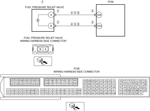
INSPECT FUEL PRESSURE RELIEF VALVE CIRCUIT FOR OPEN CIRCUIT
• Verify that the fuel pressure relief valve and PCM connectors are disconnected.
• Inspect for continuity between the following terminals (wiring harness-side):
-
― Fuel pressure relief valve terminal A—PCM terminal 1DK
― Fuel pressure relief valve terminal B—PCM terminal 1DG
• Is there continuity?
|
Yes
|
Go to the next step.
|
|
No
|
Refer to the wiring diagram and verify whether or not there is a common connector between the following terminals:
• Fuel pressure relief valve terminal A—PCM terminal 1DK
• Fuel pressure relief valve terminal B—PCM terminal 1DG
If there is a common connector:
• Determine the malfunctioning part by inspecting the common connector and the terminal for corrosion, damage, or pin disconnection, and the common wiring harness for an open circuit.
• Repair or replace the malfunctioning part.
If there is no common connector:
• Repair or replace the wiring harness which has an open circuit.
Go to Step 10.
|
|
9
|
INSPECT FUEL PRESSURE RELIEF VALVE
• Inspect the fuel pressure relief valve.
• Is there any malfunction?
|
Yes
|
Replace the common rail, then go to the next step.
|
|
No
|
Go to the next step.
|
|
10
|
VERIFY DTC TROUBLESHOOTING COMPLETED
• Always reconnect all disconnected connectors.
• Clear the DTC from the PCM memory using the M-MDS.
• Start the engine and idle it.
• Wait until the ECT PID value is above 80 °C {176 °F}.
• Wait for 1 min (idle).
• Perform the DTC Reading Procedure.
• Is the same DTC present?
|
Yes
|
Repeat the inspection from Step 1.
• If the malfunction recurs, replace the PCM.
Go to the next step.
|
|
No
|
Go to the next step.
|
|
11
|
VERIFY AFTER REPAIR PROCEDURE
• Perform the “AFTER REPAIR PROCEDURE”.
• Are any DTCs present?
|
Yes
|
Go to the applicable DTC inspection.
|
|
No
|
DTC troubleshooting completed.
|