DTC P0643:00 [PCM (SKYACTIV-D 2.2)]


id0102j5315600


Engine Type

Item

Reference

Fuel injector (2 pin type)
Fuel injector (6 pin type)


Fuel injector (2 pin type)

DTC P0643:00

Constant voltage power supply circuit high input

DETECTION CONDITION
•  When the following condition is met, the output voltage of the 5 V power supply terminal exceeds 5.144 V for a continuous 1 s:
MONITORING CONDITIONS
―  Battery voltage: 8—20 V
Diagnostic support note
•  This is a continuous monitor (CCM).
•  The check engine light illuminates if the PCM detects the above malfunction condition during the first drive cycle.
•  FREEZE FRAME DATA/Snapshot data is available.
•  DTC is stored in the PCM memory.
FAIL-SAFE FUNCTION
•  Inhibits the EGR control.
•  Inhibits engine-stop by operating the i-stop function.
POSSIBLE CAUSE
•  APP sensor connector or terminals malfunction
•  CKP sensor connector or terminals malfunction
•  MAP sensor No.2 connector or terminals malfunction
•  Engine oil temperature sensor/engine oil pressure sensor connector or terminals malfunction
•  MAF sensor/IAT sensor No.1 connector or terminals malfunction
•  Regulating valve position sensor connector or terminals malfunction
•  Power brake unit vacuum sensor connector or terminals malfunction
•  Refrigerant pressure sensor connector or terminals malfunction
•  PCM connector or terminals malfunction
•  Short to power supply in wiring harness between the following terminals:
―  APP sensor terminal A—PCM terminal 2AM
―  CKP sensor terminal A—PCM terminal 1J
―  MAP sensor No.2 terminal C—PCM terminal 1CN
―  Engine oil temperature sensor/engine oil pressure sensor terminal A—PCM terminal 1DN
―  MAF sensor/IAT sensor No.1 terminal D—PCM terminal 2AC
―  Regulating valve position sensor terminal C—PCM terminal 1BO
―  Power brake unit vacuum sensor terminal A—PCM terminal 2BB
―  Refrigerant pressure sensor terminal A—PCM terminal 2BB
•  PCM malfunction

Diagnostic Procedure

STEP

INSPECTION

ACTION

1
VERIFY FREEZE FRAME DATA/SNAPSHOT DATA HAS BEEN RECORDED
•  Has the FREEZE FRAME DATA/snapshot data been recorded?
Yes
Go to the next step.
No
Record the FREEZE FRAME DATA/snapshot data on the repair order, then go to the next step.
2
VERIFY RELATED SERVICE INFORMATION AVAILABILITY
•  Verify related Service Information availability.
•  Is any related Service Information available?
Yes
Perform repair or diagnosis according to the available Service Information.
•  If the vehicle is not repaired, go to the next step.
No
Go to the next step.
3
VERIFY RELATED PENDING CODE AND/OR DTC
•  Switch the ignition off, then ON (engine off).
•  Perform the Pending Trouble Code Access Procedure and DTC Reading Procedure.
•  Are any other PENDING CODEs and/or DTCs present?
Yes
Go to the applicable PENDING CODE or DTC inspection.
No
Go to the next step.
4
INSPECT APP SENSOR CONNECTOR CONDITION
•  Switch the ignition off.
•  Disconnect the APP sensor connector.
•  Inspect for poor connection (such as damaged/pulled-out pins, corrosion).
•  Is there any malfunction?
Yes
Repair or replace the connector and/or terminals, then go to Step 14.
No
Go to the next step.
5
INSPECT CKP SENSOR CONNECTOR CONDITION
•  Disconnect the CKP sensor connector.
•  Inspect for poor connection (such as damaged/pulled-out pins, corrosion).
•  Is there any malfunction?
Yes
Repair or replace the connector and/or terminals, then go to Step 14.
No
Go to the next step.
6
INSPECT MAP SENSOR NO.2 CONNECTOR CONDITION
•  Disconnect the MAP sensor No.2 connector.
•  Inspect for poor connection (such as damaged/pulled-out pins, corrosion).
•  Is there any malfunction?
Yes
Repair or replace the connector and/or terminals, then go to Step 14.
No
Go to the next step.
7
INSPECT ENGINE OIL TEMPERATURE SENSOR/ENGINE OIL PRESSURE SENSOR CONNECTOR CONDITION
•  Disconnect the engine oil temperature sensor/engine oil pressure sensor connector.
•  Inspect for poor connection (such as damaged/pulled-out pins, corrosion).
•  Is there any malfunction?
Yes
Repair or replace the connector and/or terminals, then go to Step 14.
No
Go to the next step.
8
INSPECT MAF SENSOR/IAT SENSOR NO.1 CONNECTOR CONDITION
•  Disconnect the MAF sensor/IAT sensor No.1 connector.
•  Inspect for poor connection (such as damaged/pulled-out pins, corrosion).
•  Is there any malfunction?
Yes
Repair or replace the connector and/or terminals, then go to Step 14.
No
Go to the next step.
9
INSPECT REGULATING VALVE POSITION SENSOR CONNECTOR CONDITION
•  Disconnect the regulating valve position sensor connector.
•  Inspect for poor connection (such as damaged/pulled-out pins, corrosion).
•  Is there any malfunction?
Yes
Repair or replace the connector and/or terminals, then go to Step 14.
No
Go to the next step.
10
INSPECT POWER BRAKE UNIT VACUUM SENSOR CONNECTOR CONDITION
•  Disconnect the power brake unit vacuum sensor connector.
•  Inspect for poor connection (such as damaged/pulled-out pins, corrosion).
•  Is there any malfunction?
Yes
Repair or replace the connector and/or terminals, then go to Step 14.
No
Go to the next step.
11
INSPECT REFRIGERANT PRESSURE SENSOR CONNECTOR CONDITION
•  Disconnect the refrigerant pressure sensor connector.
•  Inspect for poor connection (such as damaged/pulled-out pins, corrosion).
•  Is there any malfunction?
Yes
Repair or replace the connector and/or terminals, then go to Step 14.
No
Go to the next step.
12
INSPECT PCM CONNECTOR CONDITION
•  Disconnect the PCM connector.
•  Inspect for poor connection (such as damaged/pulled-out pins, corrosion).
•  Is there any malfunction?
Yes
Repair or replace the connector and/or terminals, then go to Step 14.
No
Go to the next step.
13
INSPECT EACH POWER SUPPLY CIRCUIT FOR SHORT TO POWER SUPPLY
•  Verify that the APP sensor and CKP sensor and MAP sensor No.2 and engine oil temperature sensor/engine oil pressure sensor and MAF sensor/IAT sensor No.1 and regulating valve position sensor and power brake unit vacuum sensor and refrigerant pressure sensor and PCM connectors are disconnected.
•  Switch the ignition ON (engine off).
Note
•  Another DTC may be stored by the PCM detecting an open circuit.
•  Measure the voltage at the following terminals (wiring harness-side):
―  APP sensor terminal A
―  CKP sensor terminal A
―  MAP sensor No.2 terminal C
―  Engine oil temperature sensor/engine oil pressure sensor terminal A
―  MAF sensor/IAT sensor No.1 terminal D
―  Regulating valve position sensor terminal C
―  Power brake unit vacuum sensor terminal A
―  Refrigerant pressure sensor terminal A
•  Is the voltage 0 V?
Yes
Go to the next step.
No
Refer to the wiring diagram and verify whether or not there is a common connector between the following terminals:
•  APP sensor terminal A—PCM terminal 2AM
•  CKP sensor terminal A—PCM terminal 1J
•  MAP sensor No.2 terminal C—PCM terminal 1CN
•  Engine oil temperature sensor/engine oil pressure sensor terminal A—PCM terminal 1DN
•  MAF sensor/IAT sensor No.1 terminal D—PCM terminal 2AC
•  Regulating valve position sensor terminal C—PCM terminal 1BO
•  Power brake unit vacuum sensor terminal A—PCM terminal 2BB
•  Refrigerant pressure sensor terminal A—PCM terminal 2BB
If there is a common connector:
•  Determine the malfunctioning part by inspecting the common connector and the terminal for corrosion, damage, or pin disconnection, and the common wiring harness for a short to power supply.
•  Repair or replace the malfunctioning part.
If there is no common connector:
•  Repair or replace the wiring harness which has a short to power supply.
Go to the next step.
14
VERIFY DTC TROUBLESHOOTING COMPLETED
•  Always reconnect all disconnected connectors.
•  Clear the DTC from the PCM memory using the M-MDS.
•  Switch the ignition ON (engine off) and wait for 30 s or more.
•  Perform the DTC Reading Procedure.
•  Is the same DTC present?
Yes
Repeat the inspection from Step 1.
•  If the malfunction recurs, replace the PCM.
Go to the next step.
No
Go to the next step.
15
VERIFY AFTER REPAIR PROCEDURE
•  Perform the “AFTER REPAIR PROCEDURE”.
•  Are any DTCs present?
Yes
Go to the applicable DTC inspection.
No
DTC troubleshooting completed.


Fuel injector (6 pin type)

DTC P0643:00

Constant voltage power supply circuit high input

DETECTION CONDITION
•  When the following condition is met, the output voltage of the constant voltage (5 V) power supply terminal exceeds 5.96 V for a continuous 0.5 s.
―  Battery positive voltage: 8—16 V
Diagnostic support note
•  This is a continuous monitor (CCM).
•  The check engine light illuminates if the PCM detects the above malfunction condition during the first drive cycle.
•  FREEZE FRAME DATA/Snapshot data is available.
•  DTC is stored in the PCM memory.
FAIL-SAFE FUNCTION
•  Limits the engine torque/limits the maximum engine speed.
•  Inhibits the automatic diesel particulate filter regeneration control.
•  Inhibits the intake shutter valve control.
•  Inhibits the manual diesel particulate filter regeneration control.
•  Inhibits the EGR control.
•  Stops the G-vectoring control (GVC).
•  Limits the engine transaxle total control.
•  Inhibits engine-stop by i-stop control.
POSSIBLE CAUSE
•  APP sensor connector or terminal malfunction
•  CKP sensor connector or terminal malfunction
•  MAP sensor No.2 connector or terminal malfunction
•  Engine oil temperature/engine oil pressure sensor connector or terminal malfunction
•  MAF/IAT sensor No.1 connector or terminal malfunction
•  Power brake unit vacuum sensor connector or terminal malfunction
•  Refrigerant pressure sensor connector or terminal malfunction
•  Fuel pressure sensor (integrated with fuel injector No.1) connector or terminal malfunction
•  Fuel pressure sensor (integrated with fuel injector No.4) connector or terminal malfunction
•  Variable turbine geometry turbocharger actuator/variable turbine geometry turbocharger actuator position sensor connector or terminal malfunction
•  EGR cooler bypass valve/EGR cooler bypass valve position sensor connector or terminal malfunction
•  PCM connector or terminal malfunction
•  Short to power supply in wiring harness between the following terminals
―  APP sensor terminal A and PCM terminal 2AM
―  CKP sensor terminal A and PCM terminal 1J
―  MAP sensor No.2 terminal C and PCM terminal 1CN
―  Engine oil temperature/engine oil pressure sensor terminal A and PCM terminal 1DN
―  MAF/IAT sensor No.1 terminal D and PCM terminal 2AC
―  Power brake unit vacuum sensor terminal A and PCM terminal 2BB
―  Refrigerant pressure sensor terminal C and PCM terminal 2BB
―  Fuel pressure sensor (integrated with fuel injector No.1) terminal C and PCM terminal 1M
―  Fuel pressure sensor (integrated with fuel injector No.4) terminal C and PCM terminal 1N
―  Variable turbine geometry turbocharger actuator/variable turbine geometry turbocharger actuator position sensor terminal E and PCM terminal 1BE
―  EGR cooler bypass valve/EGR cooler bypass valve position sensor terminal B and PCM terminal 1AU
•  PCM malfunction

Diagnostic Procedure

Step

Inspection

Results

Action

1
RECORD VEHICLE STATUS WHEN DTC WAS DETECTED TO UTILIZE WITH REPEATABILITY VERIFICATION
Note
•  Recording can be facilitated using the screen capture function of the PC.
•  Record the freeze frame data/snap shot data.
Go to the next step.
2
VERIFY OTHER RELATED DTCs
•  Switch the ignition OFF, and then switch it ON (engine off).
•  Display the DTCs using the M-MDS.
•  Has any DTC other than P0643:00 been stored?
Yes
Repair the malfunctioning location according to the applicable DTC troubleshooting.
No
Go to the next step.
3
INSPECT APP SENSOR CONNECTOR CONDITION
•  Switch the ignition OFF.
•  Disconnect the APP sensor connector
•  Inspect the connector engagement and connection condition, and inspect the terminals for damage, deformation, corrosion, or disconnection.
•  Is the connector normal?
Yes
Go to the next step.
No
Repair or replace the connector, then go to Step 16.
4
INSPECT CKP SENSOR CONNECTOR CONDITION
•  Disconnect the CKP sensor connector.
•  Inspect the connector engagement and connection condition, and inspect the terminals for damage, deformation, corrosion, or disconnection.
•  Is the connector normal?
Yes
Go to the next step.
No
Repair or replace the connector, then go to Step 16.
5
INSPECT MAP SENSOR NO.2 CONNECTOR CONDITION
•  Disconnect the MAP sensor No.2 connector.
•  Inspect the connector engagement and connection condition, and inspect the terminals for damage, deformation, corrosion, or disconnection.
•  Is the connector normal?
Yes
Go to the next step.
No
Repair or replace the connector, then go to Step 16.
6
INSPECT ENGINE OIL TEMPERATURE/ENGINE OIL PRESSURE SENSOR CONNECTOR CONDITION
•  Disconnect the engine oil temperature/engine oil pressure sensor connector.
•  Inspect the connector engagement and connection condition, and inspect the terminals for damage, deformation, corrosion, or disconnection.
•  Is the connector normal?
Yes
Go to the next step.
No
Repair or replace the connector, then go to Step 16.
7
INSPECT MAF/IAT SENSOR NO.1 CONNECTOR CONDITION
•  Disconnect the MAF/IAT sensor No.1 connector.
•  Inspect the connector engagement and connection condition, and inspect the terminals for damage, deformation, corrosion, or disconnection.
•  Is the connector normal?
Yes
Go to the next step.
No
Repair or replace the connector, then go to Step 16.
8
INSPECT POWER BRAKE UNIT VACUUM SENSOR CONNECTOR
•  Disconnect the power brake unit vacuum sensor connector.
•  Inspect the connector engagement and connection condition, and inspect the terminals for damage, deformation, corrosion, or disconnection.
•  Is the connector normal?
Yes
Go to the next step.
No
Repair or replace the connector, then go to Step 16.
9
INSPECT REFRIGERANT PRESSURE SENSOR CONNECTOR CONNECTION
•  Disconnect the Refrigerant pressure sensor connector.
•  Inspect the connector engagement and connection condition, and inspect the terminals for damage, deformation, corrosion, or disconnection.
•  Is the connector normal?
Yes
Go to the next step.
No
Repair or replace the connector, then go to Step 16.
10
INSPECT FUEL PRESSURE SENSOR (INTEGRATED WITH FUEL INJECTOR NO.1) CONNECTOR CONDITION
•  Disconnect the fuel pressure sensor (integrated with fuel injector No.1) connector.
•  Inspect the connector engagement and connection condition, and inspect the terminals for damage, deformation, corrosion, or disconnection.
•  Is the connector normal?
Yes
Go to the next step.
No
Repair or replace the connector, then go to Step 16.
11
INSPECT FUEL PRESSURE SENSOR (INTEGRATED WITH FUEL INJECTOR NO.4) CONNECTOR CONDITION
•  Disconnect the fuel pressure sensor (integrated with fuel injector No.4) connector.
•  Inspect the connector engagement and connection condition, and inspect the terminals for damage, deformation, corrosion, or disconnection.
•  Is the connector normal?
Yes
Go to the next step.
No
Repair or replace the connector, then go to Step 16.
12
INSPECT VARIABLE TURBINE GEOMETRY TURBOCHARGER ACTUATOR POSITION SENSOR CONNECTOR CONDITION
•  Disconnect the variable turbine geometry turbocharger actuator position sensor connector.
•  Inspect the connector engagement and connection condition, and inspect the terminals for damage, deformation, corrosion, or disconnection.
•  Is the connector normal?
Yes
Go to the next step.
No
Repair or replace the connector, then go to Step 16.
13
INSPECT EGR COOLER BYPASS VALVE/EGR COOLER BYPASS VALVE POSITION SENSOR CONNECTOR CONDITION
•  Disconnect the EGR cooler bypass valve/EGR cooler bypass valve position sensor connector.
•  Inspect the connector engagement and connection condition, and inspect the terminals for damage, deformation, corrosion, or disconnection.
•  Is the connector normal?
Yes
Go to the next step.
No
Repair or replace the connector, then go to Step 16.
14
INSPECT PCM CONNECTOR CONDITION
•  Disconnect the PCM connector.
•  Inspect the connector engagement and connection condition, and inspect the terminals for damage, deformation, corrosion, or disconnection.
•  Is the connector normal?
Yes
Go to the next step.
No
Repair or replace the connector, then go to Step 16.
15
INSPECT EACH POWER SUPPLY CIRCUIT FOR SHORT TO POWER SUPPLY
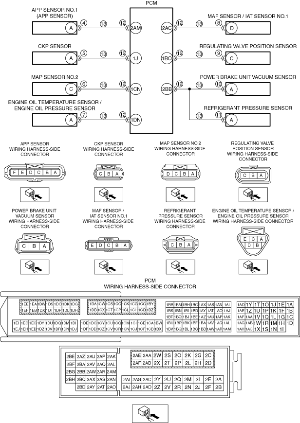
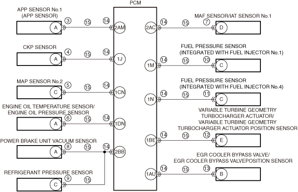
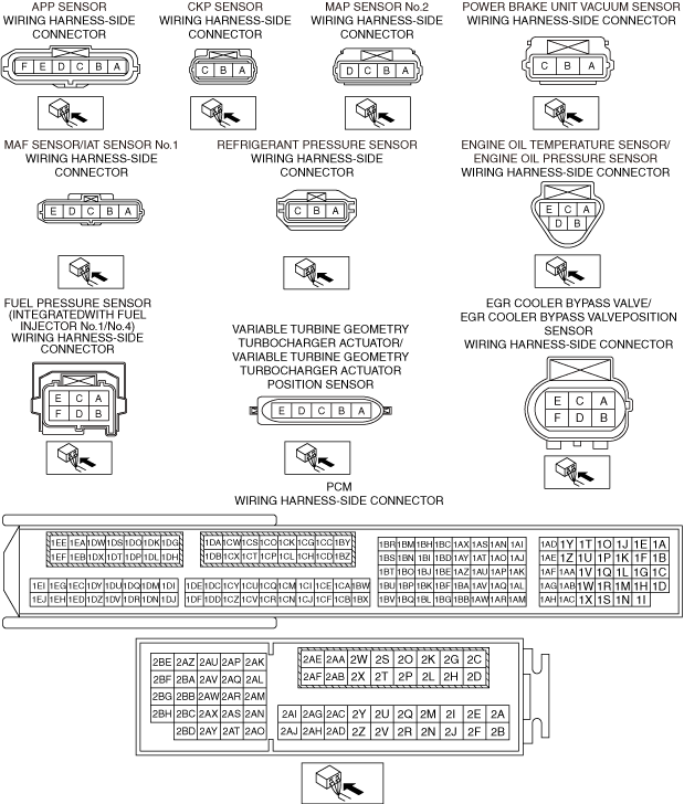
•  Verify that the APP sensor, crankshaft position sensor, MAP sensor No.2, engine oil temperature sensor/engine oil pressure sensor, MAF sensor/IAT sensor No.1, power brake unit vacuum sensor, Refrigerant pressure sensor, fuel pressure sensor (fuel injector No.1, 4 integrated), variable turbine geometry turbocharger actuator/variable turbine geometry turbocharger actuator position sensor, or EGR cooler bypass valve/EGR cooler bypass valve position sensor connector is disconnected.
•  Switch the ignition ON (engine off).
•  Measure the voltage at the following terminals (vehicle wiring harness side).
―  APP sensor terminal A
―  CKP sensor terminal A
―  MAP sensor No.2 terminal C
―  Engine oil temperature sensor/engine oil pressure sensor terminal A
―  MAF/IAT sensor No.1 terminal D
―  Power brake unit vacuum sensor terminal A
―  Refrigerant pressure sensor terminal C
―  Fuel pressure sensor (integrated with fuel injector No.1) terminal C
―  Fuel pressure sensor (integrated with fuel injector No.4) terminal C
―  Variable turbine geometry turbocharger actuator/variable turbine geometry turbocharger actuator position sensor terminal E
―  EGR cooler bypass valve/EGR cooler bypass valve position sensor terminal B
•  Is the voltage 0 V?
Yes
Go to the next step.
No
Refer to the wiring diagram and verify if there is a common connector between the following terminals.
•  APP sensor terminal A and PCM terminal 2AM
•  CKP sensor terminal A and PCM terminal 1J
•  MAP sensor No.2 terminal C and PCM terminal 1CN
•  Engine oil temperature/engine oil pressure sensor terminal A and PCM terminal 1DN
•  MAF/IAT sensor No.1 terminal D and PCM terminal 2AC
•  Power brake unit vacuum sensor terminal A and PCM terminal 2BB
•  Refrigerant pressure sensor terminal C and PCM terminal 2BB
•  Fuel pressure sensor (integrated with fuel injector No.1) terminal C and PCM terminal 1M
•  Fuel pressure sensor (integrated with fuel injector No.4) terminal C and PCM terminal 1N
•  Variable turbine geometry turbocharger actuator position sensor terminal E and PCM terminal 1BE
•  EGR cooler bypass valve/EGR cooler bypass valve position sensor terminal B and PCM terminal 1AU
If there is a common connector:
―  Inspect the common connector and terminals for corrosion, damage, or disconnection and the common wiring harnesses for short to power supply to determine the malfunctioning location.
―  Repair or replace the malfunctioning location.
If there is no common connector:
―  Repair or replace the wiring harness which is shorted to the power supply.
Go to Step 13.
16
VERIFY THAT REPAIRS HAVE BEEN COMPLETED
•  Reconnect all the disconnected connectors.
•  Refer to the [MEMORY CLEARING PROCEDURE] and clear the DTC.
•  Switch the ignition ON (engine off) and wait for 30 s.
•  Display the DTCs using the M-MDS.
•  Has DTC P0643:00 been recorded?
Yes
Repeat the inspection from Step 1.
•  If the malfunction recurs, replace the PCM, then go to the next step.
No
Go to the next step.
17
VERIFY OTHER DTCs
•  Has any other DTC or pending code been stored?
Yes
Repair the malfunctioning location according to the applicable DTC troubleshooting.
No
DTC troubleshooting completed.