 |
am6zzw00017889
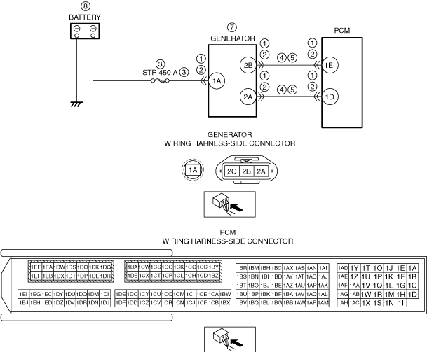
DTC P2503:00 [PCM (SKYACTIV-D 2.2)]
id0102j5709600
Details On DTCs
|
System malfunction location |
Generator system: Voltage generated by generator is low |
|
|---|---|---|
|
Detection condition
|
Determination condition
|
• A condition continues for a specified period of time in which the generator target output current calculated by the PCM is 20 A or more and the generator output voltage is 8.5 V or less.
|
|
Preconditions
|
• Engine is running
|
|
|
determination period
|
• 5 s
|
|
|
Drive cycle
|
• 1
|
|
|
Self-test type
|
• CMDTC self test
|
|
|
Sensor/unit used
|
• PCM
• Generator
|
|
|
Fail-safe
|
• Inhibits the i-stop control.
|
|
|
Vehicle status when DTCs are output
|
• i-stop warning light (amber) flashes
• A warning message is displayed on the LCD in the instrument cluster.
|
|
|
Possible cause
|
• Poor connection of the following parts:
• Connector or terminal malfunction of the following parts:
• Malfunction in the following fuses:
• Short to ground in wiring harness between the following terminals:
• Open circuit in wiring harness between the following terminals:
• Generator drive belt shear, deviation, or wear
• Malfunction in generator
• PCM malfunction
|
|
System Wiring Diagram
am6zzw00017889
|
Function Explanation (DTC Detection Outline)
Repeatability Verification Procedure
PID Item/Simulation Item Used in Diagnosis
Function Inspection Using M-MDS
|
Step |
Inspection |
Results |
Action |
|---|---|---|---|
|
1
|
PURPOSE: RECORD VEHICLE STATUS AT TIME OF DTC DETECTION TO UTILIZE WITH REPEATABILITY VERIFICATION
• Record the freeze frame data/snap shot data.
|
—
|
Go to Troubleshooting Diagnostic Procedure to perform the procedure from step 1.
|
Troubleshooting Diagnostic Procedure
|
Step |
Inspection |
Results |
Action |
|---|---|---|---|
|
1
|
PURPOSE: VERIFY IF POOR CONNECTION OF EACH PART AFFECTS DIAGNOSTIC RESULTS
• Switch the ignition OFF.
• Inspect the connection condition (part installation condition, connector connection condition) for the following parts:
• Is the connection condition (part installation condition, connector connection condition) for each part normal?
|
Yes
|
Go to the next step.
|
|
No
|
Connect each part or the connector correctly, then go to the next step.
|
||
|
2
|
PURPOSE: VERIFY IF CONNECTOR DAMAGE OF EACH PART AFFECTS DIAGNOSTIC RESULTS
• Disconnect the connectors of the following parts:
• Inspect the connector engagement and connection condition, and inspect the terminals for damage, deformation, corrosion, or disconnection.
• Is the connector normal?
|
Yes
|
Go to the next step.
|
|
No
|
Repair or replace the connector, then go to the next step.
|
||
|
3
|
PURPOSE: INSPECT FOR MALFUNCTION DUE TO BAD FUSE
• Remove the STR 450 A fuse.
• Inspect the STR 450 A fuse.
• Is the STR 450 A fuse normal?
|
Yes
|
Install all the removed fuses, then go to the next step.
|
|
No
|
If the fuse is blown:
• Refer to the wiring diagram and verify if there is a common connector between the battery positive terminal and generator terminal 1A.
If there is a common connector:
If there is no common connector:
If the fuse is damaged:
• Replace the damaged fuse.
Go to the next step.
|
||
|
4
|
PURPOSE: VERIFY IF SHORT TO GROUND IN EACH WIRING HARNESS AFFECTS DIAGNOSTIC RESULTS
• Verify that the generator and the PCM connectors are disconnected.
• Disconnect the battery connector.
• Inspect for continuity between the following terminals (vehicle wiring harness side) and ground.
• Is there continuity?
|
Yes
|
Refer to the wiring diagram and verify if there is a common connector between the following terminals.
• Generator terminal 2B and PCM terminal 1BR
• Generator terminal 2A and PCM terminal 1Z
If there is a common connector:
If there is no common connector:
Go to the next step.
|
|
No
|
Go to the next step.
|
||
|
5
|
PURPOSE: VERIFY IF OPEN CIRCUIT IN EACH WIRING HARNESS AFFECTS DIAGNOSTIC RESULTS
• Verify that the battery and generator connectors, and the PCM connector are disconnected.
• Verify that the IG1 relay is removed.
• Inspect between the following terminals (vehicle wiring harness side) for continuity.
• Is there continuity?
|
Yes
|
Go to Step 8.
|
|
No
|
Refer to the wiring diagram and verify if there is a common connector between the following terminals.
• Generator terminal 2B and PCM terminal 1EI
• Generator terminal 2A and PCM terminal 1D
If there is a common connector:
If there is no common connector:
Go to the next step.
|
||
|
6
|
PURPOSE: VERIFY IF DIAGNOSTIC RESULT IS AFFECTED BY MALFUNCTION RELATED TO GENERATOR DRIVE BELT
• Inspect the generator drive belt.
• Is the indicator mark on the drive belt auto tensioner within the normal range?
|
Yes
|
Go to the next step.
|
|
No
|
Replace the generator drive belt, then go to the next step.
|
||
|
7
|
PURPOSE: DETERMINE INTEGRITY OF GENERATOR
• Inspect the generator.
• Is the generator normal?
|
Yes
|
Go to the next step.
|
|
No
|
Replace the generator, then go to the next step.
|
||
|
8
|
PURPOSE: VERIFY BATTERY CHARGE CONDITION
• Inspect the battery.
(See BATTERY INSPECTION.)
|
—
|
Follow the inspection instructions, then go to the next step.
|
|
9
|
PURPOSE: VERIFICATION OF VEHICLE REPAIR COMPLETION
• Reconnect all disconnected connectors and hoses.
• Refer to the [MEMORY CLEARING PROCEDURE] and clear the DTC.
• Implement the repeatability verification procedure.
• Display the DTCs using the M-MDS.
• Is DTC P2503:00 displayed?
|
Yes
|
Repeat the inspection from Step 1.
• If the malfunction recurs, replace the PCM, then go to the next step.
|
|
No
|
Go to the next step.
|
||
|
10
|
PURPOSE: VERIFY IF THERE IS ANY OTHER MALFUNCTION
• Has any other DTC or pending code been stored?
|
Yes
|
Repair the malfunctioning location according to the applicable DTC troubleshooting.
|
|
No
|
DTC troubleshooting completed.
|