|
1
|
RECORD VEHICLE STATUS WHEN DTC WAS DETECTED TO UTILIZE WITH REPEATABILITY VERIFICATION
-
Note
-
• Recording can be facilitated using the screen capture function of the PC.
• Record the freeze frame data/snap shot data.
|
—
|
Go to the next step.
|
|
2
|
INSPECT REFRIGERANT PRESSURE SENSOR CONNECTOR CONDITION
• Switch the ignition OFF.
• Disconnect the Refrigerant pressure sensor connector.
• Inspect the connector engagement and connection condition, and inspect the terminals for damage, deformation, corrosion, or disconnection.
• Is the connector normal?
|
Yes
|
Go to the next step.
|
|
No
|
Repair or replace the connector, then go to Step 8.
|
|
3
|
INSPECT PCM CONNECTOR CONDITION
• Disconnect the PCM connector.
• Inspect the connector engagement and connection condition, and inspect the terminals for damage, deformation, corrosion, or disconnection.
• Is the connector normal?
|
Yes
|
Go to the next step.
|
|
No
|
Repair or replace the connector, then go to Step 8.
|
|
4
|
INSPECT REFRIGERANT PRESSURE SENSOR CIRCUIT FOR SHORT TO GROUND
• Switch the ignition OFF.
• Verify that the Refrigerant pressure sensor connector is disconnected.
• Inspect for continuity between the following terminals (vehicle wiring harness) and ground.
-
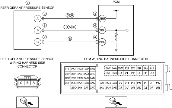
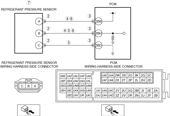
― Refrigerant pressure sensor terminal A
― Refrigerant pressure sensor terminal B
• Is there continuity?
|
Yes
|
Refer to the wiring diagram and verify if there is a common connector between the following terminals.
• Refrigerant pressure sensor terminal A and PCM terminal 2BB
• Refrigerant pressure sensor terminal B and PCM terminal 2BH
If there is a common connector:
-
― Inspect the common connector and terminals for corrosion, damage, or disconnection and the common wiring harnesses for short to ground to determine the malfunctioning location.
― Repair or replace the malfunctioning location.
If there is no common connector:
-
― Repair or replace the malfunctioning wiring harness.
Go to Step 8.
|
|
No
|
Go to the next step.
|
|
5
|
INSPECT REFRIGERANT PRESSURE SENSOR SIGNAL CIRCUIT AND GROUND CIRCUIT FOR SHORT CIRCUIT
• Verify that the Refrigerant pressure sensor connector and the PCM connector are disconnected.
• Switch the ignition OFF.
• Inspect for continuity between A/C relay sensor terminals B, A (vehicle wiring harness side).
• Is there continuity?
|
Yes
|
Refer to the wiring diagram and verify if there is a common connector between the following terminals.
• Refrigerant pressure sensor terminal B and PCM terminal 2BH
• Refrigerant pressure sensor terminal C and PCM terminal 2BD
If there is a common connector:
-
― Inspect the common connector and terminals for corrosion, damage, or disconnection and the common wiring harnesses for short circuit to determine the malfunctioning location.
― Repair or replace the malfunctioning location.
If there is no common connector:
-
― Repair or replace the malfunctioning wiring harness.
Go to Step 8.
|
|
No
|
Go to the next step.
|
|
6
|
INSPECT REFRIGERANT PRESSURE SENSOR CIRCUIT FOR OPEN CIRCUIT
• Verify that the Refrigerant pressure sensor connector and the PCM connector are disconnected.
• Inspect the wiring harness for continuity between the following terminals (vehicle wiring harness side).
-
― Refrigerant pressure sensor terminal A and PCM terminal 2BB
― Refrigerant pressure sensor terminal B and PCM terminal 2BH
• Is there continuity?
|
Yes
|
Go to the next step.
|
|
No
|
Refer to the wiring diagram and verify if there is a common connector between the following terminals.
• Refrigerant pressure sensor terminal A and PCM terminal 2BB
• Refrigerant pressure sensor terminal B and PCM terminal 2BH
If there is a common connector:
-
― Inspect the common connector and terminals for corrosion, damage, or disconnection and the common wiring harnesses for an open circuit to determine the malfunctioning location.
― Repair or replace the malfunctioning location.
If there is no common connector:
-
― Repair or replace the wiring harness which has an open circuit.
Go to Step 8.
|
|
7
|
INSPECT REFRIGERANT PRESSURE SENSOR
• Reconnect all the disconnected connectors.
• Inspect the Refrigerant pressure sensor.
• Is the Refrigerant pressure sensor normal?
|
Yes
|
Go to the next step.
|
|
No
|
Replace the Refrigerant pressure sensor, then go to the next step.
|
|
8
|
VERIFY THAT REPAIRS HAVE BEEN COMPLETED
• Reconnect all the disconnected connectors.
• Refer to the [MEMORY CLEARING PROCEDURE] and clear the DTC.
• Start the engine.
• Turn the A/C on.
• Display the DTCs using the M-MDS.
• Has DTC P0532:00 been recorded?
|
Yes
|
Repeat the inspection from Step 1.
• If the malfunction recurs, replace the PCM, then go to the next step.
|
|
No
|
Go to the next step.
|
|
9
|
VERIFY OTHER DTCs
• Has any other DTC or pending code been stored?
|
Yes
|
Repair the malfunctioning location according to the applicable DTC troubleshooting.
|
|
No
|
DTC troubleshooting completed.
|