 |
ac5uuw00006272
DTC P0130:00 [PCM (WITHOUT CYLINDER DEACTIVATION (SKYACTIV-G 2.0, SKYACTIV-G 2.5))]
id0102sc702100
Engine Type
|
Item |
Reference |
|---|---|
|
Without coolant control valve
|
|
|
With coolant control valve
|
(See With Coolant Control Valve.)
|
Without Coolant Control Valve
Details On DTCs
|
DESCRIPTION |
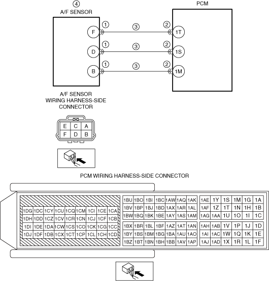
Voltage problem between PCM terminal 1AB and PCM terminal 1AG |
|
|---|---|---|
|
DETECTION CONDITION
|
Determination conditions
|
• A condition in which the voltage between PCM terminals 1AB and 1AG exceeds the specified range continues for the specified period or more.
|
|
Preconditions
|
• Switch the ignition ON (engine off or on)
• Battery voltage: 11—18 V*1
• The following DTC is not detected:
*1: Standard can be verified by displaying PIDs using M-MDS
|
|
|
Drive cycle
|
• 2
|
|
|
Self test type
|
• CMDTC self test, KOER self test
|
|
|
Sensor used
|
• A/F sensor
|
|
|
FAIL-SAFE FUNCTION
|
• Fixes duty value of A/F sensor heater
• Stops fuel feedback control of A/F sensor
|
|
|
VEHICLE STATUS WHEN DTCs ARE OUTPUT
|
• Illuminates check engine light.
|
|
|
POSSIBLE CAUSE
|
• A/F sensor connector or terminals malfunction
• PCM connector or terminals malfunction
• Deterioration in wiring harness between the following terminals:
• A/F sensor malfunction
• PCM malfunction
|
|
System Wiring Diagram
ac5uuw00006272
|
Function Explanation (DTC Detection Outline)
Repeatability Verification Procedure
PID Item/Simulation Item Used In Diagnosis
PID/DATA monitor item table
|
Item |
Definition |
Unit |
Condition/Specification |
|---|---|---|---|
|
O2S11
|
A/F sensor current
|
µA
|
• Idle (after warm up): Approx. −39 µA
• Deceleration fuel cut (accelerator pedal released from engine speed of 4,000 rpm or more): Approx. 3.84 mA
|
Function Inspection Using M-MDS
|
STEP |
INSPECTION |
RESULTS |
ACTION |
|---|---|---|---|
|
1
|
PURPOSE: VERIFY RELATED SERVICE INFORMATION AVAILABILITY
• Verify related Service Information availability.
• Is any related Service Information available?
|
Yes
|
Perform repair or diagnosis according to the available Service Information.
• If the vehicle is not repaired, go to the next step.
|
|
No
|
Go to the next step.
|
||
|
2
|
PURPOSE: RECORD FREEZE FRAME DATA/SNAPSHOT DATA AND DIAGNOSTIC MONITORING TEST RESULTS TO UTILIZE WITH REPEATABILITY VERIFICATION
• Record the FREEZE FRAME DATA/snapshot data and DIAGNOSTIC MONITORING TEST RESULTS (A/F sensor, HO2S related) on the repair order.
|
—
|
Go to the troubleshooting procedure to perform the procedure from Step 1.
|
Troubleshooting Diagnostic Procedure
|
STEP |
INSPECTION |
RESULTS |
ACTION |
|---|---|---|---|
|
1
|
PURPOSE: INSPECT A/F SENSOR CONNECTOR CONDITION
• Switch the ignition off.
• Disconnect the A/F sensor connector.
• Inspect for poor connection (such as damaged/pulled-out pins, corrosion).
• Is there any malfunction?
|
Yes
|
Repair or replace the connector and/or terminals, then go to Step 5.
|
|
No
|
Go to the next step.
|
||
|
2
|
PURPOSE: INSPECT PCM CONNECTOR CONDITION
• Disconnect the PCM connector.
• Inspect for poor connection (such as damaged/pulled-out pins, corrosion).
• Is there any malfunction?
|
Yes
|
Repair or replace the connector and/or terminals, then go to Step 5.
|
|
No
|
Go to the next step.
|
||
|
3
|
PURPOSE: INSPECT WIRING HARNESS BETWEEN A/F SENSOR AND PCM FOR DETERIORATION
• Inspect for deterioration between the following terminals (wiring harness-side):
• Is there any malfunction?
|
Yes
|
Repair or replace the wiring harness which has deteriorated, then go to Step 5.
|
|
No
|
Go to the next step.
|
||
|
4
|
PURPOSE: DETERMINE INTEGRITY OF A/F SENSOR
• Start the engine and warm it up completely.
• Access the O2S11 PID using the M-MDS.
• Drive the vehicle under the following conditions.
• Is the displayed PID value as follows?
|
Yes
|
Go to the next step.
|
|
No
|
Replace the A/F sensor, then go to the next step.
|
||
|
5
|
PURPOSE: VERIFICATION OF VEHICLE REPAIR COMPLETION
• Always reconnect all disconnected connectors.
• Clear the DTC from the PCM memory using the M-MDS.
• Perform the KOER self test.
• Is the PENDING CODE for this DTC present?
|
Yes
|
Repeat the inspection from Step 1.
• If the malfunction recurs, replace the PCM.
Go to the next step.
|
|
No
|
Go to the next step.
|
||
|
6
|
PURPOSE: VERIFY IF THERE IS ANY OTHER MALFUNCTION
• Is any other DTC or pending code stored?
|
Yes
|
Go to the applicable DTC inspection.
|
|
No
|
DTC troubleshooting completed.
|
With Coolant Control Valve
Details On DTCs
|
DESCRIPTION |
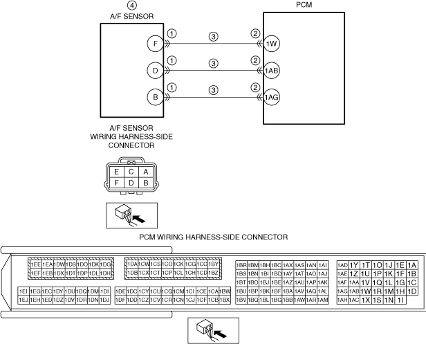
Voltage problem between PCM terminal 1S and PCM terminal 1M |
|
|---|---|---|
|
DETECTION CONDITION
|
Determination conditions
|
• A condition in which the voltage between PCM terminals 1S and 1M exceeds the specified range continues for the specified period or more.
|
|
Preconditions
|
• Switch the ignition ON (engine off or on)
• Battery voltage: 11—18 V*1
• The following DTC is not detected:
*1: Standard can be verified by displaying PIDs using M-MDS
|
|
|
Drive cycle
|
• 2
|
|
|
Self test type
|
• CMDTC self test, KOER self test
|
|
|
Sensor used
|
• A/F sensor
|
|
|
FAIL-SAFE FUNCTION
|
• Fixes duty value of A/F sensor heater
• Stops fuel feedback control of A/F sensor
|
|
|
VEHICLE STATUS WHEN DTCs ARE OUTPUT
|
• Illuminates check engine light.
|
|
|
POSSIBLE CAUSE
|
• A/F sensor connector or terminals malfunction
• PCM connector or terminals malfunction
• Deterioration in wiring harness between the following terminals:
• A/F sensor malfunction
• PCM malfunction
|
|
System Wiring Diagram
ac5uuw00009519
|
Function Explanation (DTC Detection Outline)
Repeatability Verification Procedure
PID Item/Simulation Item Used In Diagnosis
PID/DATA monitor item table
|
Item |
Definition |
Unit |
Condition/Specification |
|---|---|---|---|
|
O2S11
|
A/F sensor current
|
µA
|
• Idle (after warm up): Approx. −39 µA
• Deceleration fuel cut (accelerator pedal released from engine speed of 4,000 rpm or more): Approx. 3.84 mA
|
Function Inspection Using M-MDS
|
STEP |
INSPECTION |
RESULTS |
ACTION |
|---|---|---|---|
|
1
|
PURPOSE: VERIFY RELATED SERVICE INFORMATION AVAILABILITY
• Verify related Service Information availability.
• Is any related Service Information available?
|
Yes
|
Perform repair or diagnosis according to the available Service Information.
• If the vehicle is not repaired, go to the next step.
|
|
No
|
Go to the next step.
|
||
|
2
|
PURPOSE: RECORD FREEZE FRAME DATA/SNAPSHOT DATA AND DIAGNOSTIC MONITORING TEST RESULTS TO UTILIZE WITH REPEATABILITY VERIFICATION
• Record the FREEZE FRAME DATA/snapshot data and DIAGNOSTIC MONITORING TEST RESULTS (A/F sensor, HO2S related) on the repair order.
|
—
|
Go to the troubleshooting procedure to perform the procedure from Step 1.
|
Troubleshooting Diagnostic Procedure
|
STEP |
INSPECTION |
RESULTS |
ACTION |
|---|---|---|---|
|
1
|
PURPOSE: INSPECT A/F SENSOR CONNECTOR CONDITION
• Switch the ignition off.
• Disconnect the A/F sensor connector.
• Inspect for poor connection (such as damaged/pulled-out pins, corrosion).
• Is there any malfunction?
|
Yes
|
Repair or replace the connector and/or terminals, then go to Step 5.
|
|
No
|
Go to the next step.
|
||
|
2
|
PURPOSE: INSPECT PCM CONNECTOR CONDITION
• Disconnect the PCM connector.
• Inspect for poor connection (such as damaged/pulled-out pins, corrosion).
• Is there any malfunction?
|
Yes
|
Repair or replace the connector and/or terminals, then go to Step 5.
|
|
No
|
Go to the next step.
|
||
|
3
|
PURPOSE: INSPECT WIRING HARNESS BETWEEN A/F SENSOR AND PCM FOR DETERIORATION
• Inspect for deterioration between the following terminals (wiring harness-side):
• Is there any malfunction?
|
Yes
|
Repair or replace the wiring harness which has deteriorated, then go to Step 5.
|
|
No
|
Go to the next step.
|
||
|
4
|
PURPOSE: DETERMINE INTEGRITY OF A/F SENSOR
• Start the engine and warm it up completely.
• Access the O2S11 PID using the M-MDS.
• Drive the vehicle under the following conditions.
• Is the displayed PID value as follows?
|
Yes
|
Go to the next step.
|
|
No
|
Replace the A/F sensor, then go to the next step.
|
||
|
5
|
PURPOSE: VERIFICATION OF VEHICLE REPAIR COMPLETION
• Always reconnect all disconnected connectors.
• Clear the DTC from the PCM memory using the M-MDS.
• Perform the KOER self test.
• Is the PENDING CODE for this DTC present?
|
Yes
|
Repeat the inspection from Step 1.
• If the malfunction recurs, replace the PCM.
Go to the next step.
|
|
No
|
Go to the next step.
|
||
|
6
|
PURPOSE: VERIFY IF THERE IS ANY OTHER MALFUNCTION
• Is any other DTC or pending code stored?
|
Yes
|
Go to the applicable DTC inspection.
|
|
No
|
DTC troubleshooting completed.
|