 |
ac5wzw00011450
DTC P2B61:00 [PCM (WITH CYLINDER DEACTIVATION (SKYACTIV-G 2.0, SKYACTIV-G 2.5))]
id0102sd168000
Details On DTCs
|
DESCRIPTION |
Coolant control valve position sensor circuit range/performance |
|
|---|---|---|
|
DETECTION CONDITION
|
Determination conditions
|
• The coolant control valve control duty value is 89% or more for a continuous 2 s.
|
|
Drive cycle
|
• 1
|
|
|
Self test type
|
• CMDTC self test, KOEO self test, KOER self test
|
|
|
Sensor used
|
• Coolant control valve position sensor
|
|
|
FAIL-SAFE FUNCTION
|
• Inhibits engine-stop by operating the i-stop function.
• PCM restricts engine torque.
|
|
|
VEHICLE STATUS WHEN DTCs ARE OUTPUT
|
• Illuminates check engine light.
|
|
|
POSSIBLE CAUSE
|
• Coolant control valve/coolant control valve position sensor connector or terminals malfunction
• PCM connector or terminals malfunction
• Coolant control valve sticking, or foreign matter penetration
• Short to ground in wiring harness between the following terminals:
• Coolant control valve/coolant control valve position sensor circuits are shorted to each other
• Open circuit in wiring harness between the following terminals:
• Coolant control valve position sensor malfunction
• PCM malfunction
|
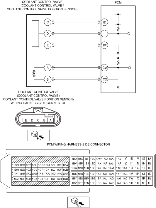
|
System Wiring Diagram
ac5wzw00011450
|
Function Explanation (DTC Detection Outline)
Repeatability Verification Procedure
1. Warm up the engine to allow the engine coolant temperature to reach 50—95 °C {122—203 °F}.
2. Try to reproduce the malfunction by driving the vehicle for 5 min based on the values in the FREEZE FRAME DATA/snapshot data.
PID Item/Simulation Item Used In Diagnosis
PID/DATA monitor item table
|
Item |
Definition |
Unit |
Condition/Specification |
|---|---|---|---|
|
ENG_CL_V_POS
|
Coolant control valve opening angle
|
°
|
• Displays target coolant control valve opening angle
|
|
ENG_CL_V_POS_R
|
Coolant control valve opening angle raw
|
°
|
• Ignition switched ON (engine off): Approx. 114 °
|
Function Inspection Using M-MDS
|
STEP |
INSPECTION |
RESULTS |
ACTION |
|---|---|---|---|
|
1
|
PURPOSE: VERIFY RELATED SERVICE INFORMATION AVAILABILITY
• Verify related Service Information availability.
• Is any related Service Information available?
|
Yes
|
Perform repair or diagnosis according to the available Service Information.
• If the vehicle is not repaired, go to the next step.
|
|
No
|
Go to the next step.
|
||
|
2
|
PURPOSE: RECORD VEHICLE STATUS AT TIME OF DTC DETECTION TO UTILIZE WITH REPEATABILITY VERIFICATION
• Record the FREEZE FRAME DATA/snapshot data on the repair order.
|
—
|
Go to the next step.
|
|
3
|
PURPOSE: VERIFY THE INPUT SIGNAL OF THE ENGINE COOLANT CONTROL VALVE POSITION SENSOR
• Ignition switched ON (engine off)
• Access the following PIDs using the M-MDS:
• Is there any signal that is far out of specification?
|
Yes
|
Go to the next step.
|
|
No
|
Go to Troubleshooting Diagnostic Procedure to perform the procedure from step 1.
|
||
|
4
|
PURPOSE: VERIFY CONNECTOR CONNECTIONS
• Start the engine.
• Access the following PIDs using the M-MDS:
• When the following parts are shaken, does the PID value include a PID item which has changed?
|
Yes
|
Inspect the related wiring harness and connector.
• Repair or replace the malfunctioning part.
|
|
No
|
Go to Troubleshooting Diagnostic Procedure to perform the procedure from step 1.
|
Troubleshooting Diagnostic Procedure
|
STEP |
INSPECTION |
RESULTS |
ACTION |
|---|---|---|---|
|
1
|
INSPECT INSTALLATION OF COOLANT CONTROL VALVE
• Inspect installation of coolant control valve.
• Is the coolant control valve installed securely?
|
Yes
|
Go to the next step.
|
|
No
|
Retighten the coolant control valve, then go to Step 7.
|
||
|
2
|
INSPECT COOLANT CONTROL VALVE CIRCUIT FOR SHORT TO GROUND
• Verify that the coolant control valve/coolant control valve position sensor and PCM connectors are disconnected.
• Inspect for continuity between the following terminals (wiring harness-side) and body ground:
• Is there continuity?
|
Yes
|
Refer to the wiring diagram and verify whether or not there is a common connector between the following terminals:
• Coolant control valve/coolant control valve position sensor terminal A—PCM terminal 1CW
• Coolant control valve/coolant control valve position sensor terminal B—PCM terminal 1CX
• Coolant control valve/coolant control valve position sensor terminal C—PCM terminal 1D
• Coolant control valve/coolant control valve position sensor terminal D—PCM terminal 1I
• Coolant control valve/coolant control valve position sensor terminal E—PCM terminal 1BG
If there is a common connector:
• Determine the malfunctioning part by inspecting the common connector and the terminal for corrosion, damage, or pin disconnection, and the common wiring harness for a short to power supply.
• Repair or replace the malfunctioning part.
If there is no common connector:
• Repair or replace the wiring harness which has a short to power supply.
Go to Step 7.
|
|
No
|
Go to the next step.
|
||
|
3
|
INSPECT COOLANT CONTROL VALVE/COOLANT CONTROL VALVE POSITION SENSOR CIRCUITS FOR SHORT TO EACH OTHER
• Verify that the coolant control valve/coolant control valve position sensor and PCM connectors are disconnected.
• Inspect for continuity between coolant control valve/coolant control valve position sensor terminals A, B, C, D and E (wiring harness-side).
• Is there continuity?
|
Yes
|
Refer to the wiring diagram and verify whether or not there is a common connector between the following terminals:
• Coolant control valve/coolant control valve position sensor terminal A—PCM terminal 1CW
• Coolant control valve/coolant control valve position sensor terminal B—PCM terminal 1CX
• Coolant control valve/coolant control valve position sensor terminal C—PCM terminal 1D
• Coolant control valve/coolant control valve position sensor terminal D—PCM terminal 1I
• Coolant control valve/coolant control valve position sensor terminal E—PCM terminal 1BG
If there is a common connector:
• Determine the malfunctioning part by inspecting the common connector and the terminal for corrosion, damage, or pin disconnection, and the common wiring harness for a short to each other.
• Repair or replace the malfunctioning part.
If there is no common connector:
• Repair or replace the wiring harness which has a short to each other.
Go to Step 7.
|
|
No
|
Go to the next step.
|
||
|
4
|
INSPECT COOLANT CONTROL VALVE CIRCUIT FOR OPEN CIRCUIT
• Verify that the coolant control valve/coolant control valve position sensor and PCM connectors are disconnected.
• Inspect for continuity between the following terminals (wiring harness-side):
• Is there continuity?
|
Yes
|
Go to the next step.
|
|
No
|
Refer to the wiring diagram and verify whether or not there is a common connector between the following terminals:
• Coolant control valve/coolant control valve position sensor terminal A—PCM terminal 1CW
• Coolant control valve/coolant control valve position sensor terminal B—PCM terminal 1CX
• Coolant control valve/coolant control valve position sensor terminal C—PCM terminal 1D
• Coolant control valve/coolant control valve position sensor terminal D—PCM terminal 1I
• Coolant control valve/coolant control valve position sensor terminal E—PCM terminal 1BG
If there is a common connector:
• Determine the malfunctioning part by inspecting the common connector and the terminal for corrosion, damage, or pin disconnection, and the common wiring harness for an open circuit.
• Repair or replace the malfunctioning part.
If there is no common connector:
• Repair or replace the wiring harness which has an open circuit.
Go to Step 7.
|
||
|
5
|
INSPECT COOLANT CONTROL VALVE
• Inspect the coolant control valve.
• Is there any malfunction?
|
Yes
|
Replace the coolant control valve, then go to Step 7.
|
|
No
|
Go to the next step.
|
||
|
6
|
INSPECT COOLANT CONTROL VALVE POSITION SENSOR
• Inspect the coolant control valve position sensor.
• Is there any malfunction?
|
Yes
|
Replace the coolant control valve, then go to the next step.
|
|
No
|
Go to the next step.
|
||
|
7
|
VERIFY DTC TROUBLESHOOTING COMPLETED
• Always reconnect all disconnected connectors.
• Clear the DTC from the PCM memory using the M-MDS.
• Implement the repeatability verification procedure.
• Perform the DTC Reading Procedure.
• Is the same DTC present?
|
Yes
|
Repeat the inspection from Step 1.
• If the malfunction recurs, replace the PCM.
Go to the next step.
|
|
No
|
Go to the next step.
|
||
|
8
|
VERIFY AFTER REPAIR PROCEDURE
• Perform the “AFTER REPAIR PROCEDURE”.
• Are any DTCs present?
|
Yes
|
Go to the applicable DTC inspection.
|
|
No
|
DTC troubleshooting completed.
|