 |
ac5wzw00010930
OIL CONTROL VALVE (OCV) FOR CYLINDER DEACTIVATION INSPECTION [WITH CYLINDER DEACTIVATION (SKYACTIV-G 2.0, SKYACTIV-G 2.5)]
id0110m2809900
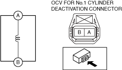
OCV for No.1 Cylinder Deactivation
Coil resistance inspection
1. Disconnect the negative battery terminal. (See NEGATIVE BATTERY TERMINAL DISCONNECTION/CONNECTION.)
2. Disconnect the OCV for No.1 cylinder deactivation connector. (See OIL CONTROL VALVE (OCV) FOR CYLINDER DEACTIVATION REMOVAL/INSTALLATION [WITH CYLINDER DEACTIVATION (SKYACTIV-G 2.0, SKYACTIV-G 2.5)].)
3. Measure the resistance between terminals A and B using an ohmmeter.
ac5wzw00010930
|
4. Install in the reverse order of removal.
Operation inspection
1. Remove the OCV for No.1 cylinder deactivation. (See OIL CONTROL VALVE (OCV) FOR CYLINDER DEACTIVATION REMOVAL/INSTALLATION [WITH CYLINDER DEACTIVATION (SKYACTIV-G 2.0, SKYACTIV-G 2.5)].)
2. Verify that the battery voltage is between 12 and 16 V. (See BATTERY INSPECTION.)
3. Connect the battery to the OCV for No.1 cylinder deactivation connector (2 terminals) as shown in the figure.
ac5wzw00010931
|
4. Verify that there is an operation sound from the OCV for No.1 cylinder deactivation when applying battery voltage between OCV for No.1 cylinder deactivation connector terminals A and B.
5. Install the OCV for No.1 cylinder deactivation. (See OIL CONTROL VALVE (OCV) FOR CYLINDER DEACTIVATION REMOVAL/INSTALLATION [WITH CYLINDER DEACTIVATION (SKYACTIV-G 2.0, SKYACTIV-G 2.5)].)
OCV for No.4 Cylinder Deactivation
Coil resistance inspection
1. Disconnect the negative battery terminal. (See NEGATIVE BATTERY TERMINAL DISCONNECTION/CONNECTION.)
2. Disconnect the OCV for No.4 cylinder deactivation connector. (See OIL CONTROL VALVE (OCV) FOR CYLINDER DEACTIVATION REMOVAL/INSTALLATION [WITH CYLINDER DEACTIVATION (SKYACTIV-G 2.0, SKYACTIV-G 2.5)].)
3. Measure the resistance between terminals A and B using an ohmmeter.
ac5wzw00010932
|
4. Install in the reverse order of removal.
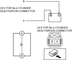
Operation inspection
1. Remove the OCV for No.4 cylinder deactivation. (See OIL CONTROL VALVE (OCV) FOR CYLINDER DEACTIVATION REMOVAL/INSTALLATION [WITH CYLINDER DEACTIVATION (SKYACTIV-G 2.0, SKYACTIV-G 2.5)].)
2. Verify that the battery voltage is between 12 and 16 V. (See BATTERY INSPECTION.)
3. Connect the battery to the OCV for No.4 cylinder deactivation connector (2 terminals) as shown in the figure.
ac5wzw00010933
|
4. Verify that there is an operation sound from the OCV for No.4 cylinder deactivation when applying battery voltage between OCV for No.4 cylinder deactivation connector terminals A and B.
5. Install the OCV for No.4 cylinder deactivation. (See OIL CONTROL VALVE (OCV) FOR CYLINDER DEACTIVATION REMOVAL/INSTALLATION [WITH CYLINDER DEACTIVATION (SKYACTIV-G 2.0, SKYACTIV-G 2.5)].)