 |
ac5uuw00006881
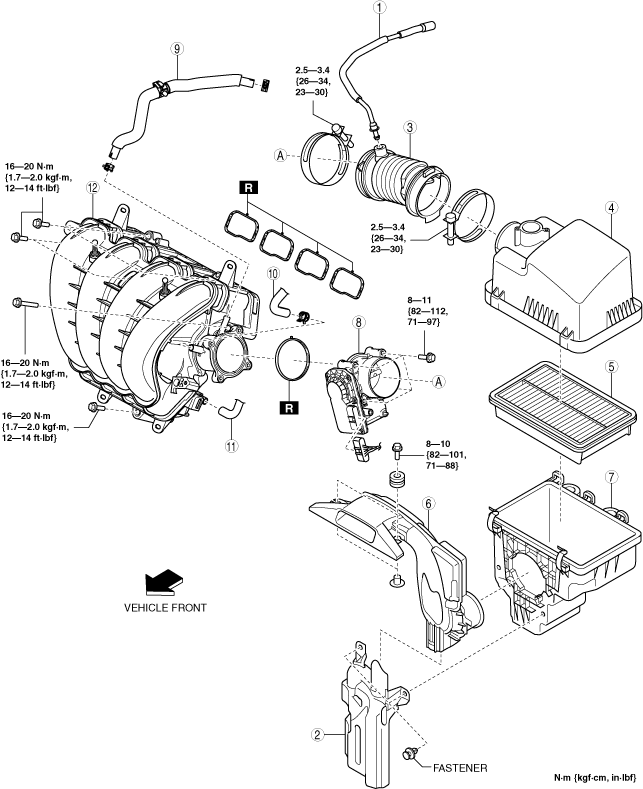
INTAKE-AIR SYSTEM REMOVAL/INSTALLATION [WITHOUT CYLINDER DEACTIVATION (SKYACTIV-G 2.0, SKYACTIV-G 2.5)]
id0113m1801900
Replacement Part
|
Intake manifold gasket
Quantity: 4
Location of use: Intake manifold
|
Throttle body gasket
Quantity: 1
Location of use: Throttle body
|
1. Disconnect the negative battery terminal. (See NEGATIVE BATTERY TERMINAL DISCONNECTION/CONNECTION.)
2. Remove in the order indicated in the table.
3. Install in the reverse order of removal.
ac5uuw00006881
|
|
1
|
Ventilation hose
|
|
2
|
Resonance chamber
|
|
3
|
Air hose
|
|
4
|
Air cleaner cover
|
|
5
|
Air cleaner element
|
|
6
|
Fresh-air duct
(See Fresh-air Duct Removal Note.)
|
|
7
|
Air cleaner case
|
|
8
|
Throttle body
(See Throttle Body Removal Note.)
|
|
9
|
Vacuum hose (between intake manifold and vacuum pump)
|
|
10
|
Evaporative hose
|
|
11
|
PCV hose
|
|
12
|
Intake manifold
|
Resonance Chamber Removal Note
1. Remove the MAF sensor/IAT sensor No.1. (See MASS AIR FLOW (MAF) SENSOR/INTAKE AIR TEMPERATURE (IAT) SENSOR NO.1 REMOVAL/INSTALLATION [WITHOUT CYLINDER DEACTIVATION (SKYACTIV-G 2.0, SKYACTIV-G 2.5)].)
2. Remove the following parts as a single unit:
3. Remove the resonance chamber.
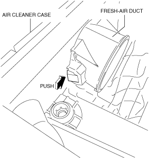
Fresh-air Duct Removal Note
1. Pull out the fresh-air duct while pressing the tab shown in the figure.
ac5uuw00000365
|
Throttle Body Removal Note
1. Remove the upper radiator hose bracket installation bolt. (See COOLING FAN MOTOR REMOVAL/INSTALLATION [WITHOUT CYLINDER DEACTIVATION (SKYACTIV-G 2.0, SKYACTIV-G 2.5)].)
2. Remove the throttle body.
Vacuum Hose (between intake manifold and vacuum pump) Removal Note
1. Remove the plug hole plate. (See PLUG HOLE PLATE REMOVAL/INSTALLATION [WITHOUT CYLINDER DEACTIVATION (SKYACTIV-G 2.0, SKYACTIV-G 2.5)].)
2. Remove the vacuum hose.
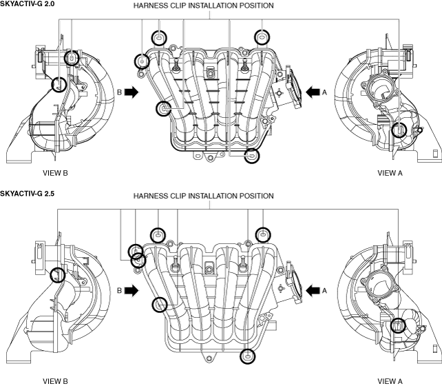
Intake Manifold Removal Note
1. Remove the MAP sensor/IAT sensor No.2. (See MANIFOLD ABSOLUTE PRESSURE (MAP) SENSOR/INTAKE AIR TEMPERATURE (IAT) SENSOR NO.2 REMOVAL/INSTALLATION [WITHOUT CYLINDER DEACTIVATION (SKYACTIV-G 2.0, SKYACTIV-G 2.5)].)
2. Disconnect the harness clip from the intake manifold as shown in the figure.
Without coolant control valve
ac5uuw00006882
|
With coolant control valve
ac5wzw00012173
|
3. Remove the intake manifold.
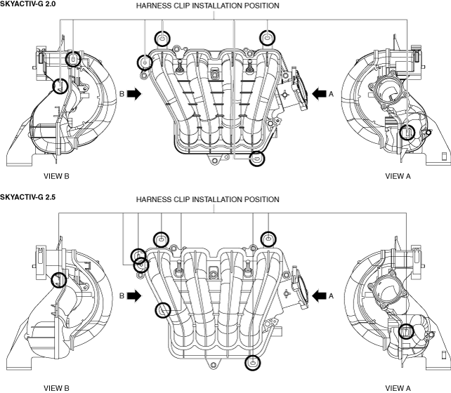
Intake Manifold Installation Note
1. Install the intake manifold.
2. Connect the wiring harness clip to the intake manifold shown in the figure.
Without coolant control valve
ac5uuw00006882
|
With coolant control valve
ac5wzw00012173
|
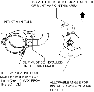
Evaporative Hose Installation Note
1. Install the evaporative hose as shown in the figure.
ac5uuw00002656
|
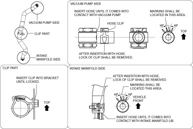
Vacuum Hose (between intake manifold and vacuum pump) Installation Note
1. Install the vacuum hose as shown in the figure.
ac5uuw00002657
|
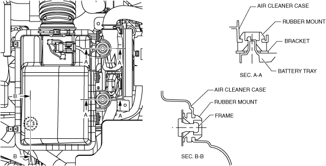
Air Cleaner Case Installation Note
1. Install the air cleaner case as shown in the figure.
ac5uuw00000367
|
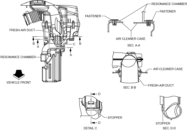
Fresh-air Duct Installation Note
1. Install the fresh-air duct as shown in the figure.
ac5uuw00000368
|
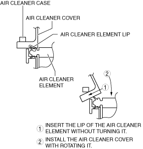
Air Cleaner Cover Installation Note
1. Install the air cleaner cover as shown in the figure.
ac5wzw00005692
|
2. Secure the air cleaner cover and the air cleaner case with the clip.
ac5wzw00010720
|
Air Hose Installation Note
1. Install the air hose as shown in the figure.
Throttle body side
ac5uuw00004520
|
Air cleaner side
ac5uuw00004521
|
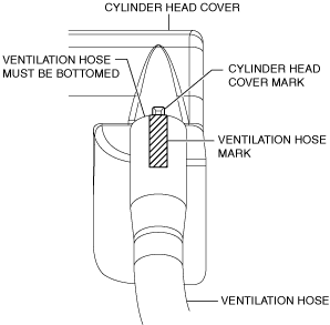
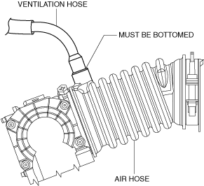
Ventilation Hose Installation Note
1. Install the ventilation hose as shown in the figure.
Cylinder head cover side
am3uuw00008002
|
Air hose side
ac5uuw00000371
|