49 0000 203
Injector bore cleaning kit

FUEL INJECTOR REMOVAL/INSTALLATION [SKYACTIV-D 2.2]
id0114z7800600
Special Service Tool (SST)
|
49 0000 203
Injector bore cleaning kit
|
|
Replacement Part
|
Clip
Quantity: 5
Location of use: Fuel return pipe (fuel injector side)
|
Nut
Quantity: 8
Location of use: Fuel injector bracket
|
Washer
Quantity: 4
Location of use: Fuel injector
|
|
Injection pipe (fuel injector side)
Quantity: 4
Location of use: Fuel injector
|
—
|
—
|
Operation After Replacing Fuel Injector
1. If the fuel injector is replaced, perform the following procedure.
Fuel injector (2pin type)
|
STEP |
ACTION |
PAGE/CONDITION |
|---|---|---|
|
1
|
Perform fuel injector code programming.
|
|
|
2
|
Perform fuel injector data reset procedure.
|
|
|
3
|
Clear the DTCs.
|
|
|
4
|
Switch the ignition off.
|
—
|
|
5
|
Wait for 20 s.
|
—
|
|
6
|
Switch the ignition ON (engine off).
|
—
|
|
7
|
Perform KOEO self-test procedure.
|
|
|
8
|
Perform KOER self-test procedure.
|
|
|
9
|
Perform fuel injector injection amount correction.
|
|
|
10
|
Clear the DTCs.
|
Fuel injector (6pin type)
|
STEP |
ACTION |
PAGE/CONDITION |
|---|---|---|
|
1
|
Clear the DTCs.
|
|
|
2
|
Switch the ignition off.
|
—
|
|
3
|
Wait for 30 s.
|
—
|
|
4
|
Switch the ignition ON (engine off).
|
—
|
|
5
|
Perform KOEO self-test procedure.
|
|
|
6
|
Perform KOER self-test procedure.
|
|
|
7
|
Perform fuel injector injection amount correction.
|
|
|
8
|
Clear the DTCs.
|
Fuel Injector Removal/Installation
1. Disconnect the negative battery terminal. (See NEGATIVE BATTERY TERMINAL DISCONNECTION/CONNECTION.)
2. Perform the “Fuel Line Safety Procedure” referring to the “BEFORE SERVICE PRECAUTION”. (See BEFORE SERVICE PRECAUTION [SKYACTIV-D 2.2].)
3. Remove the engine cover. (See ENGINE COVER REMOVAL/INSTALLATION [SKYACTIV-D 2.2].)
4. Disconnect the CMP sensor connector.
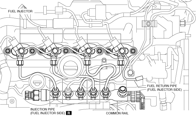
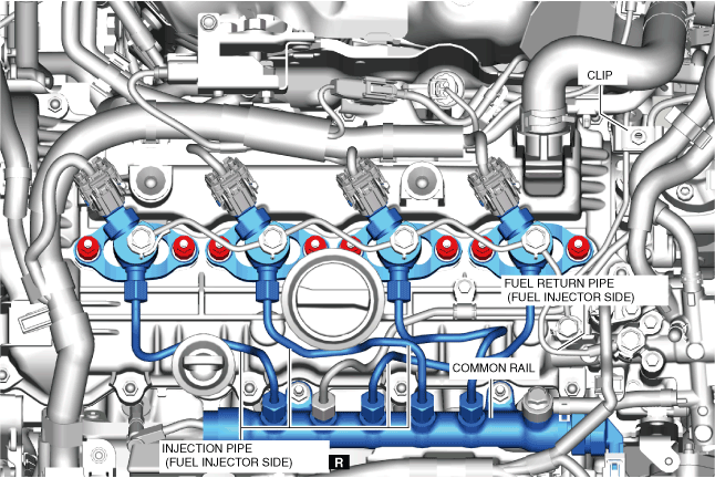
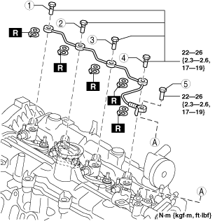
5. Remove in the order shown in the figure.
6. Install in the reverse order of removal.
7. Refer to the “AFTER SERVICE PRECAUTION” and perform the fuel hose installation procedure and fuel line air bleeding. (See AFTER SERVICE PRECAUTION [SKYACTIV-D 2.2].)
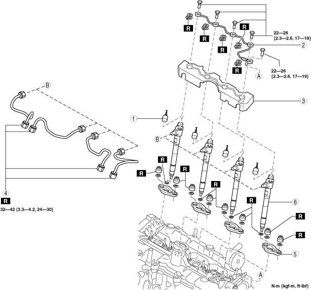
Fuel injector (2pin type)
ac5wzw00008636
|
|
1
|
Fuel injector connector
|
|
2
|
Fuel return pipe (fuel injector side)
|
|
3
|
Cover
|
|
4
|
Injection pipe (fuel injector side)
|
|
5
|
Fuel injector bracket
|
|
6
|
Fuel injector
(See Fuel injector removal note.)
|
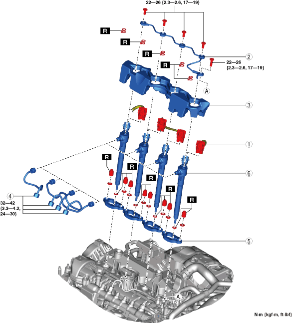
Fuel injector (6pin type)
ac5wzw00012182
|
|
1
|
Fuel injector connector
|
|
2
|
Fuel return pipe (fuel injector side)
|
|
3
|
Cover
|
|
4
|
Injection pipe (fuel injector side)
|
|
5
|
Fuel injector bracket
|
|
6
|
Fuel injector
(See Fuel injector removal note.)
|
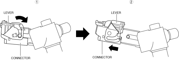
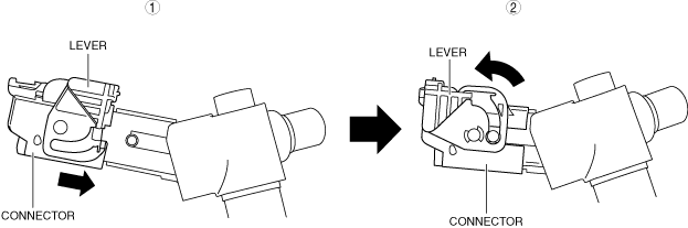
Fuel injector connector removal note (Fuel injector (6pin type))
1. Disconnect the fuel injector connector using the following procedure.
ac5wzw00012183
|
Fuel injector removal note
1. If it is difficult to remove the fuel injector, use a bar and socket set up as shown in the figure as leverage to lift the fuel injector bracket and then remove the fuel injector.
ac5wzw00008450
|
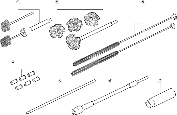
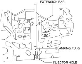
Fuel injector installation note
am6xuw00012307
|
|
1
|
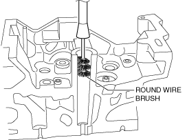
Round wire brush
|
|
2
|
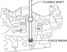
Fleece brush
|
|
3
|
Wire brush
|
|
4
|
Blanking plug
|
|
5
|
Extension bar
|
|
6
|
Flexible shaft
|
|
7
|
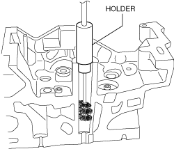
Holder
|
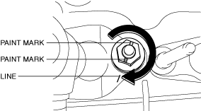
1. Install the blanking plug to the end of the extension bar.
2. Insert the blanking plug into the injector hole, rotate the extension bar counterclockwise, and then block the injector hole using the blanking plug.
am6xuw00012308
|
3. Install the round wire brush to the end of the flexible shaft.
am6xuw00012309
|
am6xuw00012310
|
4. Connect the flexible shaft installed to the round wire brush to the drill, and clean the bore.
5. Clean the carbon that was cut off using an air gun.
6. Cut (reference: diameter approx. 23 mm) the fleece brush so that it reaches the bottom surface, and install it to the flexible shaft.
7. Connect the flexible shaft installed to the fleece brush to the drill, and clean the bottom surface.
am6xuw00012311
|
8. Clean the carbon that was cut off using an air gun.
9. Insert the extension bar and remove the blanking plug.
10. Clean the injector hole using a wire brush.
am6xuw00012312
|
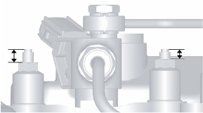
11. Temporarily install the fuel injector and the fuel injector bracket.
Fuel injector (2pin type)
ac5wzw00005780
|
Fuel injector (6pin type)
ac5wzw00012184
|
12. Loosen the common rail.
13. Temporarily tighten the new injection pipe (fuel injector side).
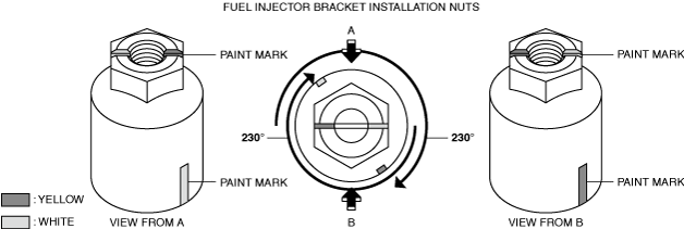
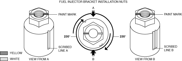
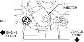
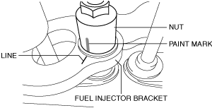
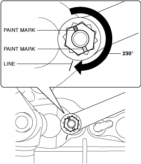
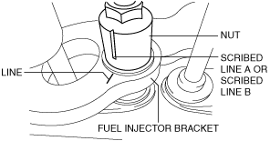
14. Tighten the new fuel injector bracket installation nuts using the following procedure.
am3zzw00016417
|
ac5wzw00011711
|
am3zzw00016418
|
am3zzw00016419
|
am3zzw00016420
|
ac5wzw00011712
|
am3zzw00016420
|
am3zzw00016421
|
aaxjjw00018823
|
15. Tighten the injection pipes (fuel injector side) on the common rail side.
16. Tighten the injection pipes (fuel injector side) on the fuel injector side.
17. Tighten the common rail.
18. Tighten the fuel return pipe (fuel injector side) in the order shown in the figure.
Fuel injector (2pin type)
ac5wzw00009507
|
Fuel injector (6pin type)
ac5wzw00012185
|
Fuel injector connector installation note Fuel injector (6pin type)
1. Connect the fuel injector connector using the following procedure.
ac5wzw00012186
|