 |
ac9wzn00001705
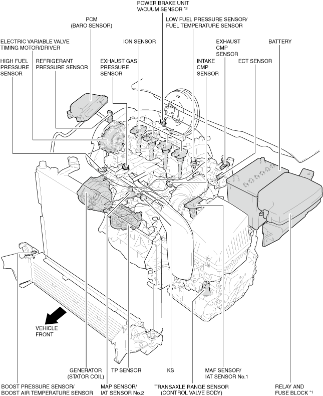
ENGINE CONTROL SYSTEM [SKYACTIV-G 2.5T]
id0140h0139900
Outline
Structure
System structure
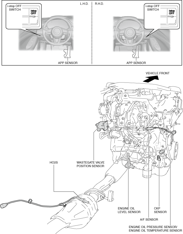
Input device
ac9wzn00001705
|
am6zzn00005703
|
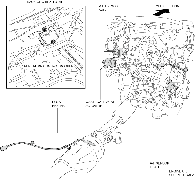
Output device
ac9uun00002328
|
am6zzn00005687
|
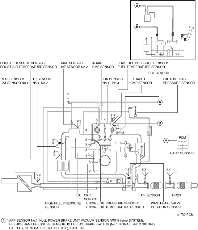
System Diagram
Input device
ac5wzn00005189
|
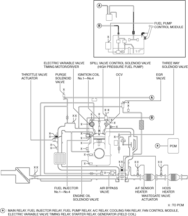
Output device
ac5wzn00005190
|
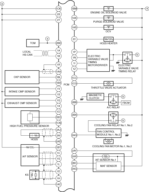
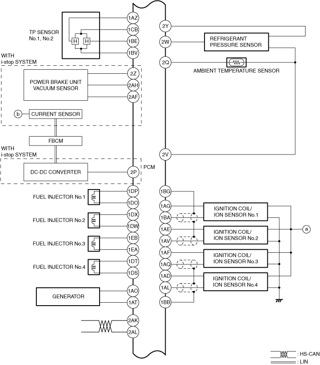
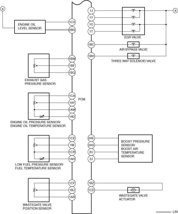
System Wiring Diagram
am6xuw00009781
|
am6zzw00017106
|
am6zzw00017107
|
am6zzw00017108
|
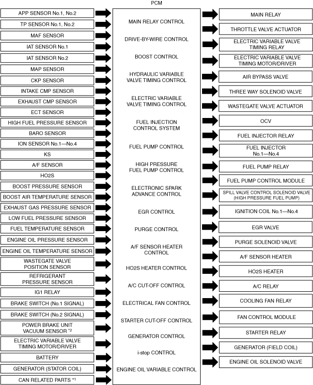
Block Diagram
ac5wzn00005335
|
Relation Chart
Input device
|
Item |
MAIN RELAY CONTROL |
DRIVE-BY-WIRE CONTROL |
BOOST CONTROL |
HYDRAULIC VARIABLE VALVE TIMING CONTROL |
ELECTRIC VARIABLE VALVE TIMING CONTROL |
FUEL INJECTION CONTROL SYSTEM |
FUEL PUMP CONTROL |
HIGH PRESSURE FUEL PUMP CONTROL |
ELECTRONIC SPARK ADVANCE CONTROL |
EGR CONTROL |
PURGE CONTROL |
AIR FUEL RATIO (A/F) SENSOR HEATER CONTROL |
HEATED OXYGEN SENSOR (HO2S) HEATER CONTROL |
A/C CUT-OFF CONTROL |
ELECTRICAL FAN CONTROL |
STARTER CUT-OFF CONTROL |
GENERATOR CONTROL |
i-stop CONTROL |
ENGINE OIL VARIABLE CONTROL |
|---|---|---|---|---|---|---|---|---|---|---|---|---|---|---|---|---|---|---|---|
|
APP sensor No.1, No.2
|
×
|
×
|
×
|
×
|
|
×
|
×
|
×
|
×
|
×
|
|||||||||
|
TP sensor No.1, No.2
|
×
|
×
|
|
×
|
×
|
×
|
|||||||||||||
|
MAF sensor
|
×
|
×
|
×
|
×
|
×
|
|
×
|
×
|
×
|
×
|
×
|
×
|
×
|
×
|
|||||
|
IAT sensor No.1
|
×
|
×
|
×
|
×
|
|
×
|
×
|
×
|
×
|
×
|
|||||||||
|
IAT sensor No.2
|
×
|
×
|
×
|
×
|
|
×
|
×
|
||||||||||||
|
MAP sensor
|
×
|
×
|
×
|
×
|
|
×
|
×
|
×
|
×
|
||||||||||
|
CKP sensor
|
×
|
×
|
×
|
×
|
×
|
×
|
×
|
×
|
×
|
×
|
×
|
×
|
×
|
×
|
×
|
×
|
×
|
×
|
|
|
Intake CMP sensor
|
×
|
×
|
×
|
|
×
|
×
|
|||||||||||||
|
Exhaust CMP sensor
|
×
|
×
|
×
|
|
×
|
×
|
×
|
×
|
|||||||||||
|
ECT sensor
|
×
|
×
|
×
|
×
|
|
×
|
×
|
×
|
×
|
×
|
×
|
×
|
×
|
×
|
×
|
×
|
|||
|
High fuel pressure sensor
|
×
|
×
|
×
|
×
|
×
|
||||||||||||||
|
BARO sensor
|
×
|
×
|
×
|
×
|
×
|
×
|
×
|
×
|
|||||||||||
|
Ion sensor No.1—No.4
|
×
|
×
|
|
||||||||||||||||
|
KS
|
|
×
|
|||||||||||||||||
|
A/F sensor
|
×
|
|
×
|
||||||||||||||||
|
HO2S
|
×
|
|
|||||||||||||||||
|
Boost pressure sensor
|
×
|
×
|
×
|
×
|
|||||||||||||||
|
Boost air temperature sensor
|
×
|
×
|
|||||||||||||||||
|
Exhaust gas pressure sensor
|
×
|
||||||||||||||||||
|
Low fuel pressure sensor
|
×
|
||||||||||||||||||
|
Fuel temperature sensor
|
×
|
||||||||||||||||||
|
Engine oil pressure sensor
|
×
|
||||||||||||||||||
|
Engine oil temperature sensor
|
×
|
||||||||||||||||||
|
Wastegate valve position sensor
|
×
|
||||||||||||||||||
|
Refrigerant pressure sensor
|
|
×
|
×
|
||||||||||||||||
|
IG1 relay
|
×
|
×
|
×
|
×
|
×
|
×
|
×
|
×
|
×
|
×
|
×
|
||||||||
|
Transaxle range sensor
|
×
|
||||||||||||||||||
|
Brake switch (No.1 signal)
|
×
|
|
×
|
||||||||||||||||
|
Brake switch (No.2 signal)
|
×
|
|
×
|
||||||||||||||||
|
Power brake unit vacuum sensor*2
|
|
×
|
|||||||||||||||||
|
Electric variable valve timing motor/driver
|
×
|
|
×
|
||||||||||||||||
|
Battery
|
×
|
×
|
×
|
×
|
×
|
×
|
×
|
×
|
|||||||||||
|
Generator (Stator coil)
|
×
|
|
|||||||||||||||||
|
CAN related parts*1
|
×
|
×
|
×
|
×
|
×
|
×
|
×
|
×
|
×
|
Output device
|
Item |
MAIN RELAY CONTROL |
DRIVE-BY-WIRE CONTROL |
BOOST CONTROL |
HYDRAULIC VARIABLE VALVE TIMING CONTROL |
ELECTRIC VARIABLE VALVE TIMING CONTROL |
FUEL INJECTION CONTROL SYSTEM |
FUEL PUMP CONTROL |
HIGH PRESSURE FUEL PUMP CONTROL |
ELECTRONIC SPARK ADVANCE CONTROL |
EGR CONTROL |
PURGE CONTROL |
AIR FUEL RATIO (A/F) SENSOR HEATER CONTROL |
HEATED OXYGEN SENSOR (HO2S) HEATER CONTROL |
A/C CUT-OFF CONTROL |
ELECTRICAL FAN CONTROL |
STARTER CUT-OFF CONTROL |
GENERATOR CONTROL |
i-stop CONTROL |
ENGINE OIL VARIABLE CONTROL |
|---|---|---|---|---|---|---|---|---|---|---|---|---|---|---|---|---|---|---|---|
|
Main relay
|
×
|
|
|||||||||||||||||
|
Throttle valve actuator
|
×
|
|
×
|
||||||||||||||||
|
Air bypass valve
|
×
|
||||||||||||||||||
|
Three way solenoid valve
|
×
|
||||||||||||||||||
|
Wastegate valve actuator
|
×
|
||||||||||||||||||
|
OCV
|
×
|
|
|||||||||||||||||
|
Electric variable valve timing relay
|
×
|
|
×
|
||||||||||||||||
|
Electric variable valve timing motor/driver
|
×
|
×
|
|
×
|
|||||||||||||||
|
Fuel injector relay
|
×
|
|
×
|
||||||||||||||||
|
Fuel injector No.1—No.4
|
×
|
|
×
|
||||||||||||||||
|
Fuel pump relay
|
×
|
||||||||||||||||||
|
Fuel pump control module
|
×
|
||||||||||||||||||
|
Spill valve control solenoid valve (High pressure fuel pump)
|
|
×
|
|||||||||||||||||
|
Ignition coil No.1—No.4
|
|
×
|
×
|
||||||||||||||||
|
EGR valve
|
×
|
||||||||||||||||||
|
Purge solenoid valve
|
|
×
|
|||||||||||||||||
|
A/F sensor heater
|
|
×
|
|||||||||||||||||
|
HO2S heater
|
|
×
|
|||||||||||||||||
|
A/C relay
|
|
×
|
|||||||||||||||||
|
Cooling fan relay
|
|
×
|
|||||||||||||||||
|
Fan control module
|
|
×
|
|||||||||||||||||
|
Starter relay
|
|
×
|
×
|
||||||||||||||||
|
Generator (Field coil)
|
|
×
|
×
|
||||||||||||||||
|
Engine oil solenoid valve
|
|
×
|