PURGE CONTROL [SKYACTIV-G 2.5T]
id0140h0203800
Outline
• By performing the purge solenoid valve control according to the engine operation conditions, introduces an appropriate amount of evaporative gas into the upstream of the turbocharger or the intake manifold to prevent release of evaporative gas into the atmosphere while ensuring driveability.
• The PCM drives the purge solenoid valve based on the signal from each control part.
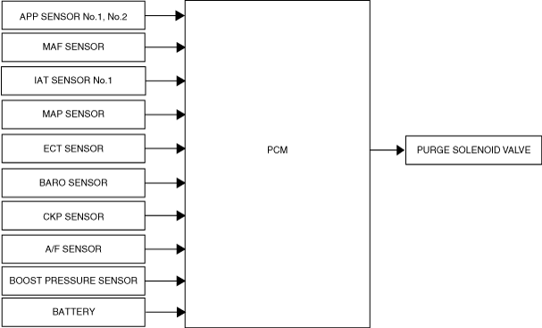
Block Diagram
Operation
• The PCM calculates the purge flow amount in 3 stages and determines the evaporative gas amount according to the engine operation conditions.
-
― Non boost range: Via purge solenoid valve and intake manifold
― Boost range: Via purge solenoid valve and ejector
― Medium boost range: Via purge solenoid valve and intake manifold, and via purge solenoid valve and ejector
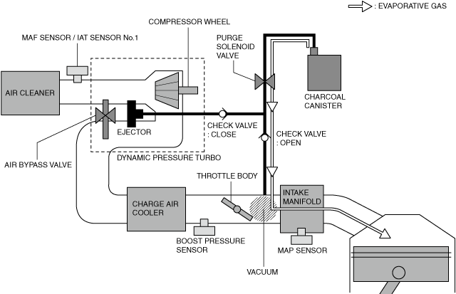
Non boost range (intake manifold vacuum is applied)
• In the non boost range, the PCM calculates the purge flow amount based on the evaporative gas density and information from the BARO sensor and the MAP sensor according to the intake manifold vacuum.
Non boost range: Via purge solenoid valve and intake manifold
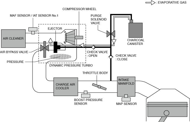
Boost range (ejector is applied)
• In the boost range, the PCM calculates the purge flow amount based on the evaporative gas density and information from the BARO sensor and the boost pressure sensor according to the ejector operation.
Boost range: Via purge solenoid valve and ejector
Medium boost stage (both intake manifold vacuum and ejector are applied)
• In the medium boost range, the PCM calculates the purge flow amount based on the evaporative gas density and information from the BARO sensor, the boost pressure sensor, and the MAP sensor according to the intake manifold vacuum and ejector operation.
Medium boost range: Via purge solenoid valve and intake manifold, and via purge solenoid valve and ejector
Determination of purge solenoid valve drive duty
-
• The PCM determines the drive duty of the purge solenoid valve which passes the purge flow based on the information such as the difference in pressure between the barometric pressure sensor and the MAP sensor or the boost pressure sensor. The drive duty is corrected by the battery voltage.
• The drive duty is corrected by the battery voltage.
Operation condition
-
• When all of the following conditions are met, the PCM drives the purge solenoid valve by the duty signal.
-
― Fuel injection control is in feedback zone (λ= 1)
― Engine coolant temperature 60 °C {140 °F} or more