 |
ac5wzw00009802
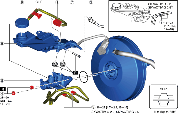
MASTER CYLINDER REMOVAL/INSTALLATION [R.H.D.]
id041100801352
Replacement Part
|
Nut
Quantity: 2
Location of use: Cylinder component
|
Set bolt
Quantity: 1
Location of use: Brake fluid reserve tank
|
Bush
Quantity: 2
Location of use: Cylinder component
|
|
O-ring
Quantity: 1
Location of use: Cylinder component
|
—
|
—
|
Oil and Chemical Type
|
Brake fluid type
Type: SAE J1703 or FMVSS116 DOT-3 or DOT-4
|
1. Disconnect the negative battery terminal. (See NEGATIVE BATTERY TERMINAL DISCONNECTION/CONNECTION.)
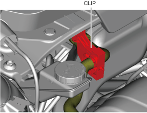
2. Remove the clip securing the cooler hose (LO).
ac5wzw00009802
|
3. Remove in the order indicated in the table.
4. Install in the reverse order of removal.
5. After installation, add brake fluid, bleed the air, and inspect for fluid leakage. (See BRAKE FLUID AIR BLEEDING.)
ac5wzw00009803
|
|
1
|
Brake fluid level sensor connector
|
|
2
|
Clutch reserve hose (MTX)
|
|
3
|
Brake pipe
|
|
4
|
Nut
|
|
5
|
Master cylinder
|
|
6
|
Cap
|
|
7
|
Brake fluid reserve tank
|
|
8
|
Cylinder component
|
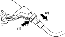
Clutch Reserve Hose Removal Note (MTX)
1. Disconnect the clutch reserve hose in the order shown in the figure.
ac5uuw00007492
|
Clutch Reserve Hose Installation Note (MTX)
1. Insert the clutch reserve hose into the master cylinder.
2. Pull the clutch reserve hose to verify that it does not come off, and reinsert it completely.