REAR ABS WHEEL-SPEED SENSOR INSPECTION [4WD]
id0415008002a5
-
Caution
-
• Do not allow a magnetized tool such as a magnetized screwdriver to come into contact with the ABS sensor rotor. If the ABS sensor rotor becomes magnetized it will be unable to read the ABS wheel speed sensor waveform correctly resulting in an ABS system malfunction to be determined and the inability to perform ABS control. If a magnetized object comes into contact with the ABS sensor rotor, it will be necessary to newly replace the rear drive shaft (ABS sensor rotor).
Installation Visual Inspection
1. Inspect the following items:
-
• If there is any malfunction, replace the applicable part.
- (1) Excessive play of the ABS wheel-speed sensor
-
- (2) Deformation of the ABS wheel-speed sensor
-
- (3) Deformation or damage of the ABS sensor rotor
-
Clearance Inspection
1. Remove the ABS wheel-speed sensor.
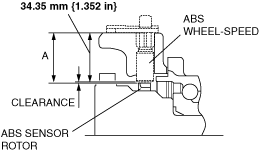
2. Measure the distance between the ABS wheel-speed sensor installation surface and the ABS sensor rotor. This is dimension A.
3. Calculate the clearance between the front ABS wheel-speed sensor and the ABS sensor rotor using the following formula:
-
Clearance (mm {in}) = A-34.35 {1.352}
4. Verify that the clearance between the ABS sensor rotor and the ABS wheel-speed sensor is as indicated below.
-
• If there is any malfunction, replace it.
-
Clearance
-
• 0.3—1.4 mm {0.02—0.05 in}
Sensor Output Value Inspection
1. Switch the ignition to off.
2. Connect the M-MDS to the DLC-2.
3. Select the following PIDs using the M-MDS:
-
• WSPD_SEN_LR (LR ABS wheel-speed sensor)
• WSPD_SEN_RR (RR ABS wheel-speed sensor)
4. Start the engine and drive the vehicle.
5. Verify that the display of the M-MDS shows the same value as the speedometer.
-
• If there is any malfunction, replace the ABS wheel-speed sensor.