 |
ac5wzw00009460
CLUTCH MASTER CYLINDER REMOVAL/INSTALLATION [C66M-R, C66MX-R]
id0510mc156800
1. Disconnect the negative battery terminal. (See NEGATIVE BATTERY TERMINAL DISCONNECTION/CONNECTION.)
2. Remove the front under cover No.2. (See FRONT UNDER COVER No.2 REMOVAL/INSTALLATION.)
3. Remove the battery. (L.H.D.) (See BATTERY REMOVAL/INSTALLATION [WITHOUT CYLINDER DEACTIVATION (SKYACTIV-G 2.0, SKYACTIV-G 2.5)].) (See BATTERY REMOVAL/INSTALLATION [WITH CYLINDER DEACTIVATION (SKYACTIV-G 2.0, SKYACTIV-G 2.5)].)
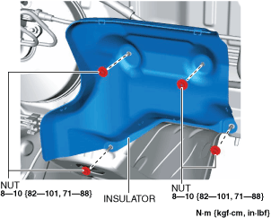
4. Remove the insulator. (R.H.D.)
ac5wzw00009460
|
5. Remove the clutch master cylinder using the following procedure. (See Clutch Master Cylinder Installation Note.)
ac5uuw00006776
|
ac5wzw00010561
|
ac5wzw00010569
|
ac5wzw00010570
|
ac5wzw00010571
|
6. Install in the reverse order of removal.
7. Fully depress the clutch pedal, and verify that the engine starts.
Clutch Master Cylinder Installation Note
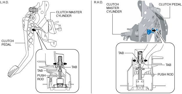
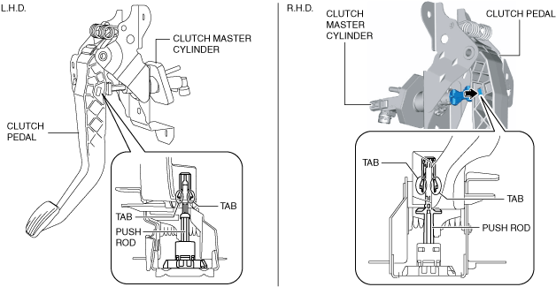
1. Engage the tabs of the push rod with the clutch pedal as shown in the figure.
ac5wzw00010572
|
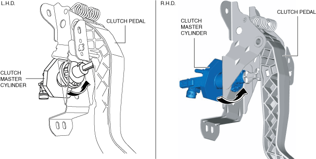
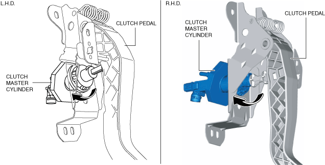
2. Rotate the clutch master cylinder in the direction shown until it stops.
ac5wzw00010573
|
3. Install the clutch pedal and the clutch master cylinder as a single unit. (See CLUTCH PEDAL REMOVAL/INSTALLATION [C66M-R, C66MX-R].)
4. Connect the clutch reserve hose to clutch master cylinder. (See CLUTCH PIPE AND HOSE REMOVAL/INSTALLATION [C66M-R, C66MX-R].)
5. Connect the clutch pipe and hose No.1 to clutch master cylinder. (See CLUTCH PIPE AND HOSE REMOVAL/INSTALLATION [C66M-R, C66MX-R].)
6. Bleed the air from the clutch system. (See CLUTCH FLUID REPLACEMENT/AIR BLEEDING [C66M-R, C66MX-R].)
7. Inspect the clutch pedal. (See CLUTCH PEDAL INSPECTION [C66M-R, C66MX-R].)
8. Install the joint cover. (See STEERING WHEEL AND COLUMN REMOVAL/INSTALLATION.)
9. Install the bracket. (See STEERING WHEEL AND COLUMN REMOVAL/INSTALLATION.)
10. Install a new starter interlock switch. (See STARTER INTERLOCK SWITCH REMOVAL/INSTALLATION [C66M-R, C66MX-R].)
11. Install a new clutch pedal position switch. (See CLUTCH PEDAL POSITION SWITCH REMOVAL/INSTALLATION [C66M-R, C66MX-R].)
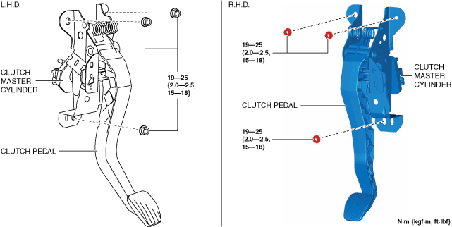
12. Connect the connectors, wiring harness clip and wiring harness shown in the figure to the clutch pedal.
ac5wzw00010561
|
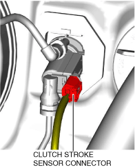
13. Connect the clutch stroke sensor connector.
ac5uuw00006776
|