CLUTCH UNIT REMOVAL/INSTALLATION [D66M-R, D66MX-R]
id0510mf157200
Special Service Tool (SST)
|
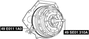
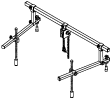
49 E011 1A0
Ring gear brake set
|
 |
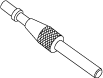
49 SE01 310A
Clutch disc center tool
|
 |
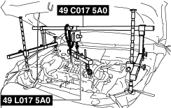
49 C017 5A0
Engine support set
|
 |
|
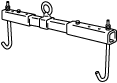
49 L017 5A0
Support hanger
|
 |
49 S120 710
Coupling flange holder
|
 |
49 G033 102
Handle
|
 |
|
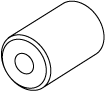
49 SE01 311
Adapter
|
 |
49 G032 354
Adjust wrench
|
 |
—
|
Replacement Part
|
Lock bolt
Quantity: 8
Location of use: Dual-mass flywheel
|
Clutch cover
Quantity: 1
Location of use: Clutch unit
|
Clutch disc
Quantity: 1
Location of use: Clutch unit
|
Oil and Chemical Type
|
Grease
Type: Molybdenum grease
|
1. Disconnect the negative battery terminal. (See NEGATIVE BATTERY TERMINAL DISCONNECTION/CONNECTION.)
2. Remove the manual transaxle. (See MANUAL TRANSAXLE REMOVAL/INSTALLATION [D66M-R].) (See MANUAL TRANSAXLE REMOVAL/INSTALLATION [D66MX-R].)
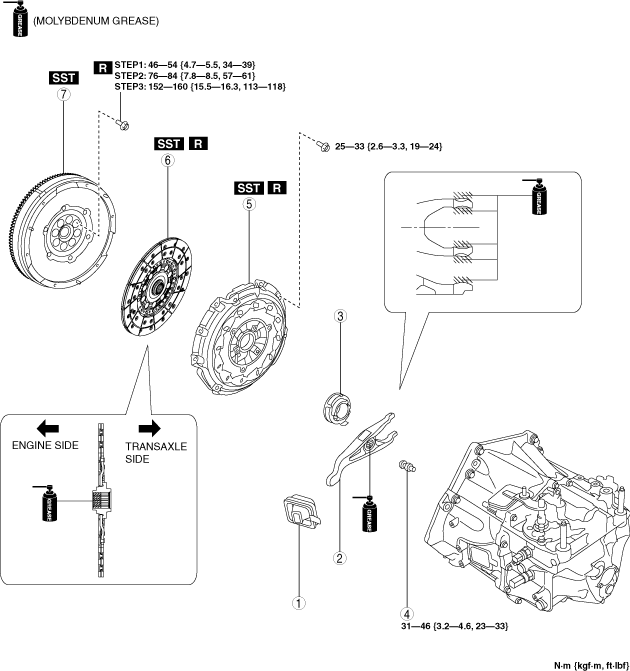
3. Remove in the order indicated in the table.
4. Install in the reverse order of removal.
5. Add the specified amount of specified manual transaxle oil. (See MANUAL TRANSAXLE OIL REPLACEMENT [D66M-R, D66MX-R].)
|
1
|
Boot
|
|
2
|
Clutch release fork
|
|
3
|
Clutch release collar
|
|
4
|
Pivot pin
|
|
5
|
Clutch cover
|
|
6
|
Clutch disc
|
|
7
|
Dual-mass flywheel
|
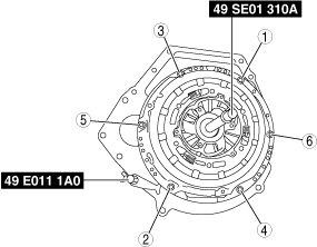
Clutch Cover and Clutch Disc Removal Note
-
Caution
-
• The removed clutch cover and clutch disc for the D66M(X)-R cannot be reused. If the clutch cover and clutch disc are removed, replace the clutch cover and clutch disc as a single unit with a new part.
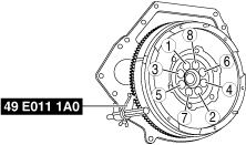
1. Install the SSTs (49 E011 1A0, 49 SE01 310A).
2. Loosen each bolt one turn at a time in a crisscross pattern until spring tension is released.
3. Remove the clutch cover and clutch disc.
Dual-mass Flywheel Removal Note
1. Verify that the SSTs (49 C017 5A0, 49 L017 5A0) support the engine securely.
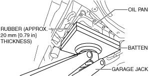
2. Support the engine using a garage jack.
-
Caution
-
• When supporting the engine, place rubber of appropriate size (approx. 20 mm {0.79 in} thickness) on a batten between the garage jack and the oil pan to prevent the deformation of the oil pan.
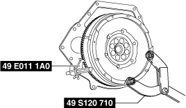
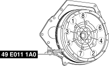
3. Lock the dual-mass flywheel against rotation using the SST (49 E011 1A0).
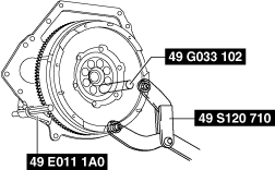
4. Loosen the lock bolts uniformly and gradually in the order shown in the figure, and remove them.
-
Note
-
• If the lock bolt installation holes are not positioned properly, perform the following procedure.
- (1) Install the SST (49 S120 710) to the dual-mass flywheel.
-
- (2) Rotate the dual-mass flywheel (secondary flywheel side) using the SST (49 S120 710).
-
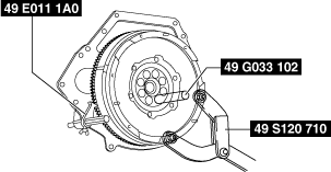
- (3) When the lock bolt installation holes are positioned properly, hold the position and remove one of the lock bolt.
-
- (4) After removing the lock bolt, set up the SST (49 G033 102) to lock the dual-mass flywheel (secondary flywheel side) against rotation.
-
-
Warning
-
• If all of the lock bolts are removed without locking the dual-mass flywheel (secondary flywheel side) against rotation, the dual-mass flywheel (primary or secondary flywheel side) may rotate, resulting in injury. Therefore, always set up the SST (49 G033 102).
• When the lock bolts are removed from the dual-mass flywheel, always cover the bolt holes using tape. If the SST (49 G033 102) is removed while the operator’s finger is inserted in the bolt hole, the dual-mass flywheel may rotate and the operator could be injured.
- (5) Remove the remaining lock bolts.
-
- (6) Remove the dual-mass flywheel.
-
-
Note
-
• When reusing the dual-mass flywheel, do not remove the SST (49 G033 102) locking the dual-mass flywheel (secondary flywheel side) against rotation.
5. Inspect for oil leakage from the crankshaft rear oil seal.
-
Dual-mass Flywheel Installation Note
1. Verify that the SSTs (49 C017 5A0, 49 L017 5A0) support the engine securely.
2. Support the engine using a garage jack.
-
Caution
-
• When supporting the engine, place rubber of appropriate size (approx. 20 mm {0.79 in} thickness) on a batten between the garage jack and the oil pan to prevent the deformation of the oil pan.
3. Clean the dual-mass flywheel.
-
Caution
-
• When cleaning the dual-mass flywheel, use a dry cloth with no fluid.
• Do not clean between the primary flywheel and secondary flywheel. Clean only the bolt connecting areas and the contact surface of the clutch.
4. Clean the crankshaft thread holes.
5. Install the dual-mass flywheel to the crankshaft.
6. Lock the dual-mass flywheel against rotation using the SST (49 E011 1A0).
7. Temporarily tighten the new lock bolts.
-
Note
-
• If the dual-mass flywheel (secondary flywheel side) is not positioned properly, perform the following procedure to install it.
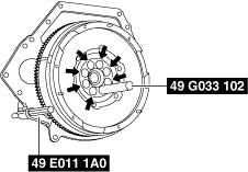
- (1) Temporarily tighten the new lock bolts to the position as shown in the figure.
-
- (2) Install the SST (49 S120 710) to the dual-mass flywheel.
-
- (3) Rotate the dual-mass flywheel (secondary flywheel side) using the SST (49 S120 710), and then temporarily tighten the remaining new lock bolt after removing the SST (49 G033 102).
-
8. Tighten the lock bolts completely in the order shown in the figure in the following 3 steps.
-
Tightening torque
-
Step 1: 46—54 N·m {4.7—5.5 kgf·m, 34—39 ft·lbf}
Step 2: 76—84 N·m {7.8—8.5 kgf·m, 57—61 ft·lbf}
Step 3: 152—160 N·m {15.5—16.3 kgf·m, 113—118 ft·lbf}
Clutch Disc Installation Note
-
Caution
-
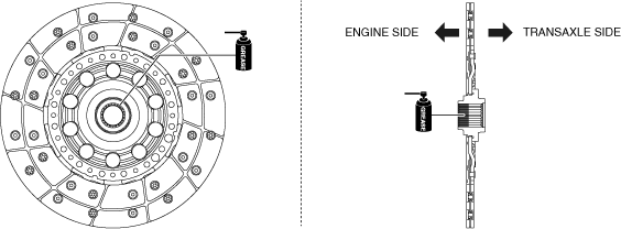
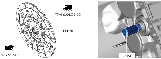
• Do not apply grease to the spline end (transaxle side). If excessive grease is applied, clutch-slip may occur.
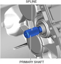
1. Clean the spline of the new clutch disc and the primary shaft with a brush.
2. Apply grease to the spline (engine side) of the clutch disc.
3. Insert the clutch disc into the primary shaft and wipe off the excess grease protruding from the spline.
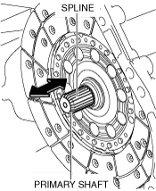
4. Slide the clutch disc three times in the directions of the arrows shown in the figure to engage to grease.
5. Remove the clutch disc from the primary shaft and wipe off the excess grease protruding from the spline.
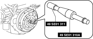
6. Verify that grease has been lightly applied to the clutch disc and the spline of the primary shaft.
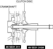
7. Install the SST (49 SE01 311) to the SST (49 SE01 310A) as shown in the figure.
8. Insert the end of the assembled SSTs into the crankshaft end, align the center of the clutch disc with the center of the flywheel, and secure them using the SSTs as shown in the figure.
Clutch Cover Installation Note
1. Install the new clutch cover while aligning the guide pins.
2. Install the SST (49 E011 1A0).
3. Tighten the bolts in the order shown in the figure.
-
Tightening torque
-
25—33 N·m {2.6—3.3 kgf·m, 19—24 ft·lbf}
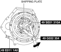
4. While holding the SST (49 SE01 310A) so that the center position of the clutch disc does not deviate, remove the shipping plate using the SST (49 G032 354).
5. Dispose of the shipping plate after removal.
6. Remove the SSTs.
-
Note
-
• When removing the SSTs, the SST (49 SE01 311) installed to the end of the SST (49 SE01 310A) may remain inside the crankshaft end. In this case, make an L-shape hook using wire, hook it through the hole at the end of the SST (49 SE01 311), and pull it out.