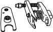
49 T028 3A0
Ball joint puller set
TIE-ROD END REPLACEMENT
id061300801200
Special Service Tool (SST)
|
49 T028 3A0
Ball joint puller set
|
|
Replacement Part
|
Snap pin
Quantity: 1
Location of use: Tie-rod end
|
1. Remove the wheel and tire. (See WHEEL AND TIRE REMOVAL/INSTALLATION.)
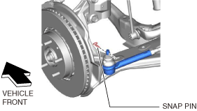
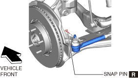
2. Remove the snap pin from the tie-rod end.
ac5uuw00006359
|
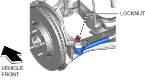
3. Loosen the tie-rod end locknut.
ac5uuw00006360
|
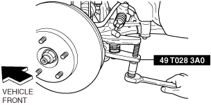
4. Detach the tie-rod end from the steering knuckle using the SST.
ac5uuw00006361
|
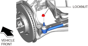
5. Remove the locknut from the tie-rod end.
ac5uuw00006362
|
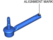
6. Place alignment marks as shown in the figure for proper installation.
ac5uuw00006363
|
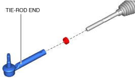
7. Remove the tie-rod end.
ac5uuw00006364
|
8. Place alignment marks on the new tie-rod end in the same positions as the removed tie-rod end.
ac5uuw00006365
|
9. Place alignment marks as shown in the figure for proper installation.
ac5uuw00006366
|
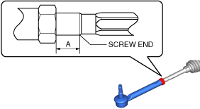
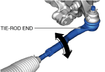
10. Adjust dimension A shown in the figure to the standard, then assemble the tie-rod end.
ac5wzw00013818
|
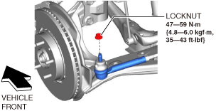
11. Install the tie-rod end to the steering knuckle.
ac5uuw00006368
|
12. Install a new snap pin to the tie-rod end.
ac5uuw00006369
|
13. Install the wheel and tire. (See WHEEL AND TIRE REMOVAL/INSTALLATION.)
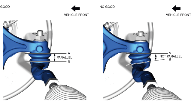
14. Verify that A and B shown in the figure are parallel while the vehicle is on the ground.
ac5wzw00013819
|
am2zzw00015169
|
15. After installation, inspect the front wheel alignment and adjust it if necessary. (See FRONT WHEEL ALIGNMENT.)