 |
am3zzw00017263
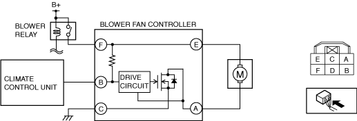
BLOWER FAN CONTROLLER INSPECTION
id071100006200
1. Disconnect the negative battery terminal. (See NEGATIVE BATTERY TERMINAL DISCONNECTION/CONNECTION.)
2. Remove the following parts:
3. Remove the blower fan controller. (See BLOWER FAN CONTROLLER REMOVAL/INSTALLATION.)
4. Connect the blower fan controller connector.
5. Connect the negative battery terminal. (See NEGATIVE BATTERY TERMINAL DISCONNECTION/CONNECTION.)
6. Switch the ignition ON (engine off or on).
7. Connect the negative (-) lead of the tester to body ground.
8. Insert the positive (+) lead of the tester into each blower fan controller terminal.
9. Measure the voltage according to the terminal voltage table.
am3zzw00017263
|
Terminal Voltage Table (Reference) (Full-auto Air Conditioner)
|
Terminal |
Signal name |
Connected to |
Measurement condition |
Voltage (V) |
Inspection item (s) |
|
|---|---|---|---|---|---|---|
|
A
|
Motor operation (-)
|
Blower motor
|
Switch the ignition off
|
1.0 or less
|
• Blower motor
• Related wiring harness
|
|
|
Fan stopped (Switch the ignition ON (engine off or on))
|
B+
|
|||||
|
Fan: manual 1st
|
8.4
|
|||||
|
Fan: manual 3rd
|
6.1
|
|||||
|
Fan: manual 7th
|
1.0 or less
|
|||||
|
B
|
Blower fan speed control
|
Climate control unit
|
• Related wiring harness
• Climate control unit
|
|||
|
C
|
GND
|
Body ground
|
Under any condition
|
1.0 or less
|
• Related wiring harness
|
|
|
D
|
—
|
—
|
—
|
—
|
—
|
|
|
E
|
Motor operation (+)
|
Blower motor
|
Switch the ignition off
|
1.0 or less
|
• Blower motor
• Related wiring harness
|
|
|
Switch the ignition ON (engine off or on)
|
B+
|
|||||
|
F
|
B+
|
Blower relay
|
Switch the ignition off
|
1.0 or less
|
• Related wiring harness
• Blower relay
|
|
|
Switch the ignition ON (engine off or on)
|
B+
|
|||||
Terminal Voltage Table (Reference) (Manual Air Conditioner)
|
Terminal |
Signal name |
Connected to |
Measurement condition |
Voltage (V) |
Inspection item (s) |
|
|---|---|---|---|---|---|---|
|
A
|
Motor operation (-)
|
Blower motor
|
Switch the ignition off
|
1.0 or less
|
• Blower motor
• Related wiring harness
|
|
|
Fan stopped (Switch the ignition ON (engine off or on))
|
B+
|
|||||
|
Fan: manual 1st
|
8.3
|
|||||
|
Fan: manual 3rd
|
5.7
|
|||||
|
Fan: manual 7th
|
1.0 or less
|
|||||
|
B
|
Blower fan speed control
|
Climate control unit
|
• Related wiring harness
• Climate control unit
|
|||
|
C
|
GND
|
Body ground
|
Under any condition
|
1.0 or less
|
• Related wiring harness
|
|
|
D
|
—
|
—
|
—
|
—
|
—
|
|
|
E
|
Motor operation (+)
|
Blower motor
|
Switch the ignition off
|
1.0 or less
|
• Blower motor
• Related wiring harness
|
|
|
Switch the ignition ON (engine off or on)
|
B+
|
|||||
|
F
|
B+
|
Blower relay
|
Switch the ignition off
|
1.0 or less
|
• Related wiring harness
• Blower relay
|
|
|
Switch the ignition ON (engine off or on)
|
B+
|
|||||
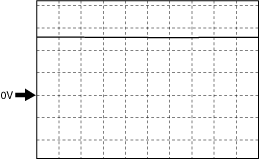
Blower Fan Speed Control Signal
Fan stopped
ac5jjw00008823
|
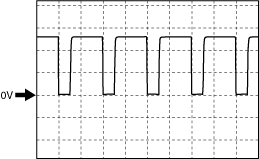
Manual 1st
ac5jjw00008824
|
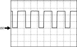
Manual 3rd
ac5jjw00008825
|
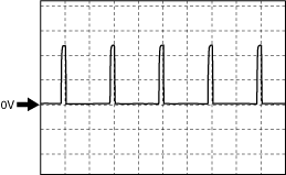
Manual 7th
ac5jjw00008826
|