 |
ac5wzn00004133
PARKING ASSIST SYSTEM [WITH CENTER DISPLAY]
id0920zz014000
With Side Camera
Outline
Functions
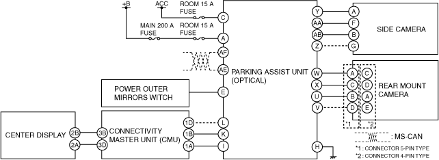
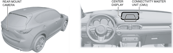
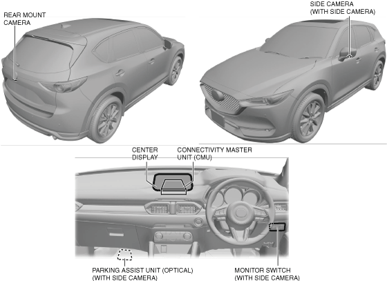
Structural view
ac5wzn00004133
|
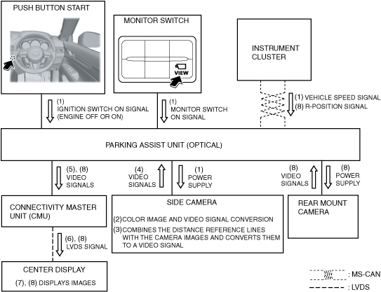
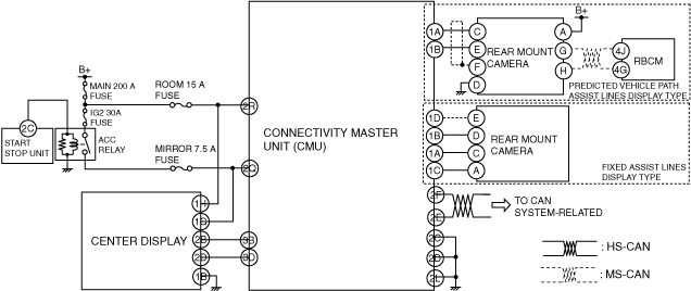
System wiring diagram
ac5wzn00004744
|
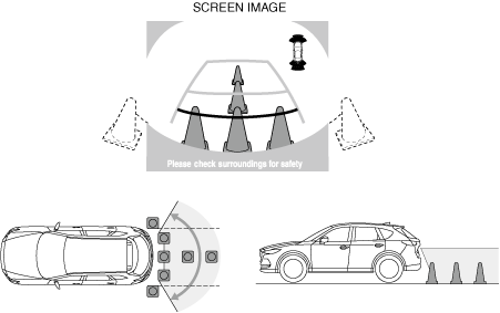
Image range
ac5wzn00004134
|
ac5wzn00004135
|
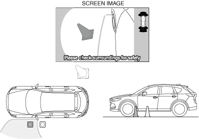
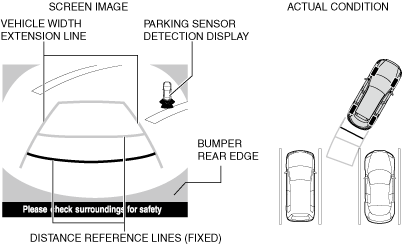
Side monitor display
ac5wzn00004136
|
|
Display item |
Display line color |
Content |
|---|---|---|
|
Distance reference line (fixed)
|
Yellow
|
• Line for indicating the vehicle end.
|
|
Yellow
|
• Extension line on the left side of the vehicle offset for outer mirrors.
|
|
|
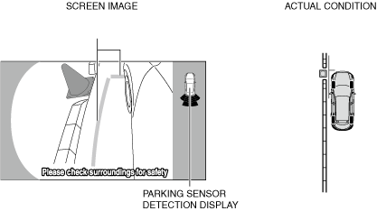
Parking sensor detection display
|
—
|
• Icon for indicating detection/non-detection of the parking sensor. (With parking sensor system)
|
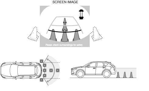
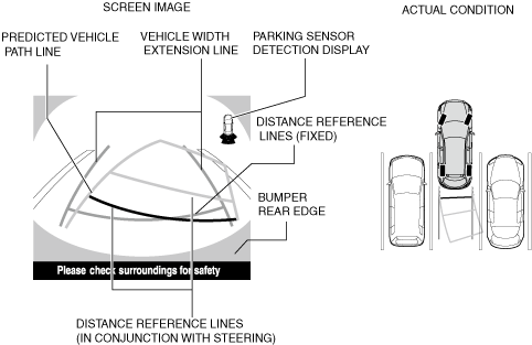
Rear view monitor display
ac5wzn00004137
|
|
Display item |
Display line color |
Content |
|---|---|---|
|
Distance reference lines (fixed)
|
Red
|
• Shows distance reference line 0.5 m {20 in} from the rear of the rear bumper.
• Not in conjunction with steering operation.
|
|
Yellow
|
• Shows distance reference line 1.0 m {39 in} from the rear of the rear bumper.
• Not in conjunction with steering operation.
|
|
|
Yellow
|
• Shows distance reference line 2.0 m {79 in} from the rear of the rear bumper.
• Not in conjunction with steering operation.
|
|
|
Vehicle width extension line
|
Yellow
|
• Vehicle width extension line.
|
|
Parking sensor detection display
|
—
|
• Icon for indicating detection/non-detection of the parking sensor. (With parking sensor system)
|
Operation
ac5wzn00004138
|
ac5wzn00004139
|
Without Side Camera
Outline
Functions
Structural view
ac5wzn00004140
|
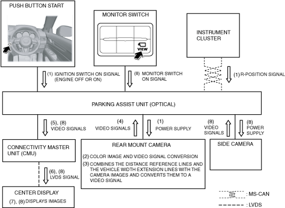
System wiring diagram
am6zzn00003717
|
Image range
ac5wzn00004141
|
Rear view monitor display (With fixed assist lines display type)
ac5wzn00004142
|
|
Display item |
Display line color |
Content |
|---|---|---|
|
Distance reference lines (fixed)
|
Red
|
• Shows distance reference line 0.5 m {20 in} from the rear of the rear bumper.
• Not in conjunction with steering operation.
|
|
Yellow
|
• Shows distance reference line 1.0 m {39 in} from the rear of the rear bumper.
• Not in conjunction with steering operation.
|
|
|
Yellow
|
• Shows distance reference line 2.0 m {79 in} from the rear of the rear bumper.
• Not in conjunction with steering operation.
|
|
|
Vehicle width extension line
|
Yellow
|
• Vehicle width extension line.
|
|
Parking sensor detection display
|
—
|
• Icon for indicating detection/non-detection of the parking sensor. (With parking sensor system)
|
Rear view monitor display (With predicted vehicle path assist lines display type)
ac5wzn00004143
|
|
Display item |
Display line color |
Content |
|---|---|---|
|
Distance reference line (in conjunction with steering)
|
Red
|
• Shows distance reference line 0.5 m {20 in} from the rear of the rear bumper.
|
|
Yellow
|
• Shows distance reference line 1.0 m {39 in} from the rear of the rear bumper.
|
|
|
Yellow
|
• Shows distance reference line 2.0 m {79 in} from the rear of the rear bumper.
|
|
|
Distance reference lines (fixed)
|
Blue
|
• Shows distance reference line 0.5 m {20 in} from the rear of the rear bumper.
• Not in conjunction with steering operation.
|
|
Vehicle width extension line
|
Blue
|
• Vehicle width extension line.
|
|
Predicted vehicle path line
|
Yellow
|
• Calculated vehicle path based on steering angle signal.
|
|
Parking sensor detection display
|
—
|
• Icon for indicating detection/non-detection of the parking sensor. (With parking sensor system)
|
Operation
ac5wzn00004144
|
ac5wzn00004145
|