DETERMINING OPEN CIRCUIT LOCATION (HS-CAN) [SKYACTIV-G 2.0/2.5, SKYACTIV-D 2.2 (MTX) (R.H.D.)]
id100239000400
-
Caution
-
• If the malfunctioning part is detected in the communication line, before disconnecting the related connector for inspection, press the connector in the connection direction to verify that there is no looseness or disconnection.
• When disconnecting the connector, verify that there is no damage, deformation, or corrosion of the connector terminals.
1. Verify the CAN system-related module DTCs and the failed module on the M-MDS screen.
2. Apply the communication error DTC and the failed module to DTC output pattern and malfunctioning location, and select the possible cause for the diagnostic result and the reference for the inspection item. (See DTC Output Pattern And Malfunctioning Location.)
-
Note
-
• The open circuit location can be determined by the DTC indicated in the DTC output pattern and malfunctioning location chart. DTCs not listed in the chart are not used for the determination of the open circuit location. (See
DTC Output Pattern And Malfunctioning Location.)
3. Inspect the possible cause and inspection item of the applicable malfunctioning part.
4. After repairs, return to CONTROLLER AREA NETWORK (CAN) MALFUNCTION DIAGNOSIS FLOW, and verify that the repairs have been completed. (See CONTROLLER AREA NETWORK (CAN) MALFUNCTION DIAGNOSIS FLOW [SKYACTIV-G 2.0/2.5, SKYACTIV-D 2.2 (MTX) (R.H.D.)].)
DTC Output Pattern And Malfunctioning Location
Cross (×): Communication error-related DTC and failed module
|
M-MDS display
|
DTC
|
DTC output pattern and malfunctioning location
|
|
DTC output module
|
|
PCM
(PCM)
|
U0101:00
|
|
|
|
|
×
|
|
|
|
|
|
|
|
|
|
|
|
|
|
|
|
|
|
|
|
|
|
|
|
|
|
|
|
U0104:00
|
|
|
×
|
|
|
|
|
|
|
|
|
|
|
|
|
|
|
|
|
|
|
|
|
|
|
|
|
|
|
|
|
|
U010E:00
|
|
|
|
|
|
|
|
|
|
|
|
|
|
×
|
|
|
|
|
|
|
|
|
|
|
|
|
|
|
|
|
|
|
U0121:00
|
|
×
|
|
|
|
|
|
|
|
|
|
|
|
|
|
|
|
|
|
|
|
|
|
|
|
|
|
|
|
|
|
|
U0131:00
|
|
|
|
|
|
|
|
|
|
|
|
|
|
|
|
|
|
|
|
|
|
|
|
|
|
×
|
|
|
|
|
|
|
U0140:00
|
|
|
|
|
|
|
×
|
|
|
|
|
|
|
|
|
|
|
|
|
|
|
|
|
|
|
|
|
|
|
|
|
|
U0151:00
|
|
|
|
|
|
|
|
|
|
|
|
|
|
|
|
|
|
|
|
|
|
|
|
×
|
|
|
|
|
|
|
|
|
U0155:00
|
|
|
|
|
|
|
|
|
|
|
|
|
|
|
|
|
|
|
|
|
|
|
|
|
|
|
|
|
×
|
|
×
|
|
U0214:00
|
|
|
|
|
|
|
|
|
|
|
|
|
|
|
|
|
|
|
|
|
|
|
|
|
|
|
×
|
|
|
|
|
|
U023A:00
|
|
|
|
|
|
|
|
|
|
|
|
|
|
|
|
|
|
|
|
|
|
×
|
|
|
|
|
|
|
|
|
|
|
U029D:00
|
|
|
|
|
|
|
|
|
|
|
|
|
×
|
|
|
|
|
|
|
|
|
|
|
|
|
|
|
|
|
|
|
|
ABS
(DSC HU/CM)
|
U0100:00
|
×
|
|
|
|
|
|
|
|
|
|
|
|
|
|
|
|
|
|
|
|
|
|
|
|
|
|
|
|
|
|
|
|
U0101:00
|
|
|
|
|
×
|
|
|
|
|
|
|
|
|
|
|
|
|
|
|
|
|
|
|
|
|
|
|
|
|
|
|
|
U0104:00
|
|
|
×
|
|
|
|
|
|
|
|
|
|
|
|
|
|
|
|
|
|
|
|
|
|
|
|
|
|
|
|
|
|
U0114:00
|
|
|
|
|
|
|
|
|
|
|
|
|
|
|
|
|
|
×
|
|
|
|
|
|
|
|
|
|
|
|
|
|
|
U0128:00
|
|
|
|
|
|
|
|
|
|
|
|
|
|
|
|
|
×
|
|
|
|
|
|
|
|
|
|
|
|
|
|
|
|
U0131:00
|
|
|
|
|
|
|
|
|
|
|
|
|
|
|
|
|
|
|
|
|
|
|
|
|
|
×
|
|
|
|
|
|
|
U0151:00
|
|
|
|
|
|
|
|
|
|
|
|
|
|
|
|
|
|
|
|
|
|
|
|
×
|
|
|
|
|
|
|
|
|
U0155:00
|
|
|
|
|
|
|
|
|
|
|
|
|
|
|
|
|
|
|
|
|
|
|
|
|
|
|
|
|
×
|
|
×
|
|
U023A:00
|
|
|
|
|
|
|
|
|
|
|
|
|
|
|
|
|
|
|
|
|
|
×
|
|
|
|
|
|
|
|
|
|
|
SBS/MRCC*1
(Radar unit)
|
U0100:00
|
×
|
|
|
|
|
|
|
|
|
|
|
|
|
|
|
|
|
|
|
|
|
|
|
|
|
|
|
|
|
|
|
|
U0101:00
|
|
|
|
|
×
|
|
|
|
|
|
|
|
|
|
|
|
|
|
|
|
|
|
|
|
|
|
|
|
|
|
|
|
U0121:00
|
|
×
|
|
|
|
|
|
|
|
|
|
|
|
|
|
|
|
|
|
|
|
|
|
|
|
|
|
|
|
|
|
|
U0131:00
|
|
|
|
|
|
|
|
|
|
|
|
|
|
|
|
|
|
|
|
|
|
|
|
|
|
×
|
|
|
|
|
|
|
U0140:00
|
|
|
|
|
|
|
×
|
|
|
|
|
|
|
|
|
|
|
|
|
|
|
|
|
|
|
|
|
|
|
|
|
|
U0151:00
|
|
|
|
|
|
|
|
|
|
|
|
|
|
|
|
|
|
|
|
|
|
|
|
×
|
|
|
|
|
|
|
|
|
U0155:00
|
|
|
|
|
|
|
|
|
|
|
|
|
|
|
|
|
|
|
|
|
|
|
|
|
|
|
|
|
×
|
|
×
|
|
U0214:00
|
|
|
|
|
|
|
|
|
|
|
|
|
|
|
|
|
|
|
|
|
|
|
|
|
|
|
×
|
|
|
|
|
|
U023A:00
|
|
|
|
|
|
|
|
|
|
|
|
|
|
|
|
|
|
|
|
|
|
×
|
|
|
|
|
|
|
|
|
|
|
TCM*2
(TCM)
|
U0100:00
|
×
|
|
|
×
|
|
|
|
|
|
|
|
|
|
|
|
|
|
|
|
|
|
|
|
|
|
|
|
|
|
|
|
|
U0121:00
|
|
×
|
|
×
|
|
|
|
|
|
|
|
|
|
|
|
|
|
|
|
|
|
|
|
|
|
|
|
|
|
|
|
|
U0131:00
|
|
|
|
|
|
|
|
|
|
|
|
|
|
|
|
|
|
|
|
|
|
|
|
|
|
×
|
|
|
|
|
|
|
U0155:00
|
|
|
|
|
|
|
|
|
|
|
|
|
|
|
|
|
|
|
|
|
|
|
|
|
|
|
|
|
×
|
|
×
|
|
U0214:00
|
|
|
|
|
|
|
|
|
|
|
|
|
|
|
|
|
|
|
|
|
|
|
|
|
|
|
×
|
|
|
|
|
|
F_BCM
(Front body control module (FBCM))
|
U0100:00
|
×
|
|
|
×
|
|
×
|
|
|
|
|
|
|
|
|
|
|
|
|
|
|
|
|
|
|
|
|
|
|
|
|
|
|
U0101:00
|
|
|
|
|
×
|
×
|
|
|
|
|
|
|
|
|
|
|
|
|
|
|
|
|
|
|
|
|
|
|
|
|
|
|
U0121:00
|
|
×
|
|
×
|
|
×
|
|
|
|
|
|
|
|
|
|
|
|
|
|
|
|
|
|
|
|
|
|
|
|
|
|
|
U0151:00
|
|
|
|
|
|
|
|
|
|
|
|
|
|
|
|
|
|
|
|
|
|
|
|
×
|
|
|
|
|
|
|
|
|
U0155:00
|
|
|
|
|
|
|
|
|
|
|
|
|
|
|
|
|
|
|
|
|
|
|
|
|
|
|
|
|
×
|
|
×
|
|
U0214:00
|
|
|
|
|
|
|
|
|
|
|
|
|
|
|
|
|
|
|
|
|
|
|
|
|
|
|
×
|
|
|
|
|
|
U023A:00
|
|
|
|
|
|
|
|
|
|
|
|
|
|
|
|
|
|
|
|
|
|
×
|
|
|
|
|
|
|
|
|
|
|
AFS/ALM
(Adaptive front lighting system (AFS) control module)
|
U0100:00
|
×
|
|
|
×
|
|
×
|
|
×
|
|
|
|
|
|
|
|
|
|
|
|
|
|
|
|
|
|
|
|
|
|
|
|
|
U0131:00
|
|
|
|
|
|
|
|
|
|
|
|
|
|
|
|
|
|
|
|
|
|
|
|
|
|
×
|
|
|
|
|
|
|
U0140:00
|
|
|
|
|
|
|
×
|
×
|
|
|
|
|
|
|
|
|
|
|
|
|
|
|
|
|
|
|
|
|
|
|
|
|
U0155:00
|
|
|
|
|
|
|
|
|
|
|
|
|
|
|
|
|
|
|
|
|
|
|
|
|
|
|
|
|
×
|
|
×
|
|
AFS/ALM
(Auto leveling control module)
|
U0100:00
|
×
|
|
|
×
|
|
×
|
|
×
|
|
|
|
|
|
|
|
|
|
|
|
|
|
|
|
|
|
|
|
|
|
|
|
|
U0140:00
|
|
|
|
|
|
|
×
|
×
|
|
|
|
|
|
|
|
|
|
|
|
|
|
|
|
|
|
|
|
|
|
|
|
|
U0155:00
|
|
|
|
|
|
|
|
|
|
|
|
|
|
|
|
|
|
|
|
|
|
|
|
|
|
|
|
|
×
|
|
×
|
|
AFS/ALM
(Adaptive LED headlights control module)
|
U0100:00
|
×
|
|
|
×
|
|
×
|
|
×
|
|
|
|
|
|
|
|
|
|
|
|
|
|
|
|
|
|
|
|
|
|
|
|
|
U0121:00
|
|
×
|
|
×
|
|
×
|
|
×
|
|
|
|
|
|
|
|
|
|
|
|
|
|
|
|
|
|
|
|
|
|
|
|
|
U0131:00
|
|
|
|
|
|
|
|
|
|
|
|
|
|
|
|
|
|
|
|
|
|
|
|
|
|
×
|
|
|
|
|
|
|
U0140:00
|
|
|
|
|
|
|
×
|
×
|
|
|
|
|
|
|
|
|
|
|
|
|
|
|
|
|
|
|
|
|
|
|
|
|
U0155:00
|
|
|
|
|
|
|
|
|
|
|
|
|
|
|
|
|
|
|
|
|
|
|
|
|
|
|
|
|
×
|
|
×
|
|
U0214:00
|
|
|
|
|
|
|
|
|
|
|
|
|
|
|
|
|
|
|
|
|
|
|
|
|
|
|
×
|
|
|
|
|
|
U023A:00
|
|
|
|
|
|
|
|
|
|
|
|
|
|
|
|
|
|
|
|
|
|
×
|
|
|
|
|
|
|
|
|
|
|
PLG*3
(Power liftgate (PLG) control module)
|
U0100:00
|
×
|
|
|
×
|
|
×
|
|
×
|
|
×
|
|
|
|
|
|
|
|
|
|
|
|
|
|
|
|
|
|
|
|
|
|
|
U0101:00
|
|
|
|
|
×
|
×
|
|
×
|
|
×
|
|
|
|
|
|
|
|
|
|
|
|
|
|
|
|
|
|
|
|
|
|
|
U0155:00
|
|
|
|
|
|
|
|
|
|
|
|
|
|
|
|
|
|
|
|
|
|
|
|
|
|
|
|
|
×
|
|
×
|
|
U0214:00
|
|
|
|
|
|
|
|
|
|
|
|
|
|
|
|
|
|
|
|
|
|
|
|
|
|
|
×
|
|
|
|
|
|
SCR*4
(Dosing control unit)
|
U0100:00
|
×
|
|
|
×
|
|
×
|
|
×
|
|
×
|
|
×
|
|
|
|
|
|
|
|
|
|
|
|
|
|
|
|
|
|
|
|
|
EPB
(Electric parking brake control module)
|
U0100:00
|
×
|
|
|
×
|
|
×
|
|
×
|
|
×
|
|
×
|
|
|
×
|
|
|
|
|
|
|
|
|
|
|
|
|
|
|
|
|
|
U0101:00
|
|
|
|
|
×
|
×
|
|
×
|
|
×
|
|
×
|
|
|
×
|
|
|
|
|
|
|
|
|
|
|
|
|
|
|
|
|
|
U0121:00
|
|
×
|
|
×
|
|
×
|
|
×
|
|
×
|
|
×
|
|
|
×
|
|
|
|
|
|
|
|
|
|
|
|
|
|
|
|
|
|
U0151:00
|
|
|
|
|
|
|
|
|
|
|
|
|
|
|
|
|
|
|
|
|
|
|
|
×
|
|
|
|
|
|
|
|
|
U0155:00
|
|
|
|
|
|
|
|
|
|
|
|
|
|
|
|
|
|
|
|
|
|
|
|
|
|
|
|
|
×
|
|
×
|
|
4×4*6
(4WD control module)
|
U0100:00
|
×
|
|
|
×
|
|
×
|
|
×
|
|
×
|
|
×
|
|
|
×
|
|
|
|
|
|
|
|
|
|
|
|
|
|
|
|
|
|
U0101:00
|
|
|
|
|
×
|
×
|
|
×
|
|
×
|
|
×
|
|
|
×
|
|
|
|
|
|
|
|
|
|
|
|
|
|
|
|
|
|
U0121:00
|
|
×
|
|
×
|
|
×
|
|
×
|
|
×
|
|
×
|
|
|
×
|
|
|
|
|
|
|
|
|
|
|
|
|
|
|
|
|
|
DSM*7
(Position memory control module)
|
U0100:00
|
×
|
|
|
×
|
|
×
|
|
×
|
|
×
|
|
×
|
|
|
×
|
|
|
|
×
|
|
|
|
|
|
|
|
|
|
|
|
|
|
U0101:00
|
|
|
|
|
×
|
×
|
|
×
|
|
×
|
|
×
|
|
|
×
|
|
|
|
×
|
|
|
|
|
|
|
|
|
|
|
|
|
|
U0151:00
|
|
|
|
|
|
|
|
|
|
|
|
|
|
|
|
|
|
|
|
|
|
|
|
×
|
|
|
|
|
|
|
|
|
U0155:00
|
|
|
|
|
|
|
|
|
|
|
|
|
|
|
|
|
|
|
|
|
|
|
|
|
|
|
|
|
×
|
|
×
|
|
U0214:00
|
|
|
|
|
|
|
|
|
|
|
|
|
|
|
|
|
|
|
|
|
|
|
|
|
|
|
×
|
|
|
|
|
|
FSC*8
(Forward sensing camera (FSC))
|
U0100:00
|
×
|
|
|
×
|
|
×
|
|
×
|
|
×
|
|
×
|
|
|
×
|
|
|
|
×
|
|
×
|
|
|
|
|
|
|
|
|
|
|
|
U0104:00
|
|
|
×
|
×
|
|
×
|
|
×
|
|
×
|
|
×
|
|
|
×
|
|
|
|
×
|
|
×
|
|
|
|
|
|
|
|
|
|
|
|
U0121:00
|
|
×
|
|
×
|
|
×
|
|
×
|
|
×
|
|
×
|
|
|
×
|
|
|
|
×
|
|
×
|
|
|
|
|
|
|
|
|
|
|
|
U0131:00
|
|
|
|
|
|
|
|
|
|
|
|
|
|
|
|
|
|
|
|
|
|
|
|
|
|
×
|
|
|
|
|
|
|
U0140:00
|
|
|
|
|
|
|
×
|
×
|
|
×
|
|
×
|
|
|
×
|
|
|
|
×
|
|
×
|
|
|
|
|
|
|
|
|
|
|
|
U0151:00
|
|
|
|
|
|
|
|
|
|
|
|
|
|
|
|
|
|
|
|
|
|
|
|
×
|
|
|
|
|
|
|
|
|
U0155:00
|
|
|
|
|
|
|
|
|
|
|
|
|
|
|
|
|
|
|
|
|
|
|
|
|
|
|
|
|
×
|
|
×
|
|
U0156:00
|
|
|
|
|
|
|
|
|
|
|
|
|
|
|
|
|
|
|
|
|
|
|
|
|
|
|
|
×
|
|
|
|
|
U0182:00
|
|
|
|
|
|
|
|
|
×
|
×
|
|
×
|
|
|
×
|
|
|
|
×
|
|
×
|
|
|
|
|
|
|
|
|
|
|
|
U0214:00
|
|
|
|
|
|
|
|
|
|
|
|
|
|
|
|
|
|
|
|
|
|
|
|
|
|
|
×
|
|
|
|
|
|
RCM
(SAS control module)
|
U0100:00
|
×
|
|
|
×
|
|
×
|
|
×
|
|
×
|
|
×
|
|
|
×
|
|
|
|
×
|
|
×
|
|
×
|
|
|
|
|
|
|
|
|
|
U0101:00
|
|
|
|
|
×
|
×
|
|
×
|
|
×
|
|
×
|
|
|
×
|
|
|
|
×
|
|
×
|
|
×
|
|
|
|
|
|
|
|
|
|
U0155:00
|
|
|
|
|
|
|
|
|
|
|
|
|
|
|
|
|
|
|
|
|
|
|
|
|
|
|
|
|
×
|
|
×
|
|
EPS
(EPS control module
|
U0100:00
|
×
|
|
|
×
|
|
×
|
|
×
|
|
×
|
|
×
|
|
|
×
|
|
|
|
×
|
|
×
|
|
×
|
|
×
|
|
|
|
|
|
|
|
U0121:00
|
|
×
|
|
×
|
|
×
|
|
×
|
|
×
|
|
×
|
|
|
×
|
|
|
|
×
|
|
×
|
|
×
|
|
×
|
|
|
|
|
|
|
|
U0126:00
|
|
|
|
|
|
|
|
|
|
|
|
|
|
|
|
|
|
|
|
|
|
|
|
×
|
×
|
|
|
|
|
|
|
|
U0155:00
|
|
|
|
|
|
|
|
|
|
|
|
|
|
|
|
|
|
|
|
|
|
|
|
|
|
|
|
|
×
|
|
×
|
|
U0214:00
|
|
|
|
|
|
|
|
|
|
|
|
|
|
|
|
|
|
|
|
|
|
|
|
|
|
|
×
|
|
|
|
|
|
U023A:00
|
|
|
|
|
|
|
|
|
|
|
|
|
|
|
|
|
|
|
|
|
|
×
|
×
|
|
×
|
|
|
|
|
|
|
|
SSU
(Start stop unit)
|
U0100:00
|
×
|
|
|
×
|
|
×
|
|
×
|
|
×
|
|
×
|
|
|
×
|
|
|
|
×
|
|
×
|
|
×
|
|
×
|
|
|
|
|
|
|
|
U0101:00
|
|
|
|
|
×
|
×
|
|
×
|
|
×
|
|
×
|
|
|
×
|
|
|
|
×
|
|
×
|
|
×
|
|
×
|
|
|
|
|
|
|
|
U0121:00
|
|
×
|
|
×
|
|
×
|
|
×
|
|
×
|
|
×
|
|
|
×
|
|
|
|
×
|
|
×
|
|
×
|
|
×
|
|
|
|
|
|
|
|
U0121:87
|
|
×
|
|
×
|
|
×
|
|
×
|
|
×
|
|
×
|
|
|
×
|
|
|
|
×
|
|
×
|
|
×
|
|
×
|
|
|
|
|
|
|
|
U0131:00
|
|
|
|
|
|
|
|
|
|
|
|
|
|
|
|
|
|
|
|
|
|
|
|
|
|
×
|
|
|
|
|
|
|
U0140:00
|
|
|
|
|
|
|
×
|
×
|
|
×
|
|
×
|
|
|
×
|
|
|
|
×
|
|
×
|
|
×
|
|
×
|
|
|
|
|
|
|
|
U0146:00
|
|
|
|
|
|
|
|
|
|
|
|
|
|
|
|
|
|
|
|
|
|
|
|
|
|
|
|
|
×
|
|
×
|
|
U0151:00
|
|
|
|
|
|
|
|
|
|
|
|
|
|
|
|
|
|
|
|
|
|
|
|
×
|
×
|
|
|
|
|
|
|
|
U0155:00
|
|
|
|
|
|
|
|
|
|
|
|
|
|
|
|
|
|
|
|
|
|
|
|
|
|
|
|
|
×
|
|
×
|
|
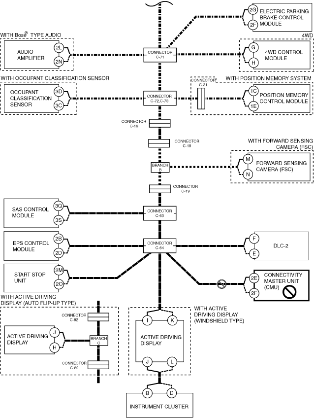
CMU*9
(Connectivity master unit (CMU))
|
U0100:00
|
×
|
|
|
×
|
|
×
|
|
×
|
|
×
|
|
×
|
|
|
×
|
|
|
|
×
|
|
×
|
|
×
|
|
×
|
|
|
|
|
|
|
|
U0101:00
|
|
|
|
|
×
|
×
|
|
×
|
|
×
|
|
×
|
|
|
×
|
|
|
|
×
|
|
×
|
|
×
|
|
×
|
|
|
|
|
|
|
|
U0104:00
|
|
|
×
|
×
|
|
×
|
|
×
|
|
×
|
|
×
|
|
|
×
|
|
|
|
×
|
|
×
|
|
×
|
|
×
|
|
|
|
|
|
|
|
U0121:00
|
|
×
|
|
×
|
|
×
|
|
×
|
|
×
|
|
×
|
|
|
×
|
|
|
|
×
|
|
×
|
|
×
|
|
×
|
|
|
|
|
|
|
|
U0131:00
|
|
|
|
|
|
|
|
|
|
|
|
|
|
|
|
|
|
|
|
|
|
|
|
|
|
×
|
|
|
|
|
|
|
U0140:00
|
|
|
|
|
|
|
×
|
×
|
|
×
|
|
×
|
|
|
×
|
|
|
|
×
|
|
×
|
|
×
|
|
×
|
|
|
|
|
|
|
|
U0151:00
|
|
|
|
|
|
|
|
|
|
|
|
|
|
|
|
|
|
|
|
|
|
|
|
×
|
×
|
|
|
|
|
|
|
|
U0155:00
|
|
|
|
|
|
|
|
|
|
|
|
|
|
|
|
|
|
|
|
|
|
|
|
|
|
|
|
|
×
|
|
×
|
|
U0182:00
|
|
|
|
|
|
|
|
|
×
|
×
|
|
×
|
|
|
×
|
|
|
|
×
|
|
×
|
|
×
|
|
×
|
|
|
|
|
|
|
|
U0214:00
|
|
|
|
|
|
|
|
|
|
|
|
|
|
|
|
|
|
|
|
|
|
|
|
|
|
|
×
|
|
|
|
|
|
U0235:00
|
|
|
|
|
|
|
|
|
|
|
|
|
|
|
|
|
|
|
|
|
|
×
|
×
|
|
×
|
|
|
|
|
|
|
|
U023A:00
|
|
|
|
|
|
|
|
|
|
|
|
|
|
|
|
|
|
|
|
|
|
×
|
×
|
|
×
|
|
|
|
|
|
|
|
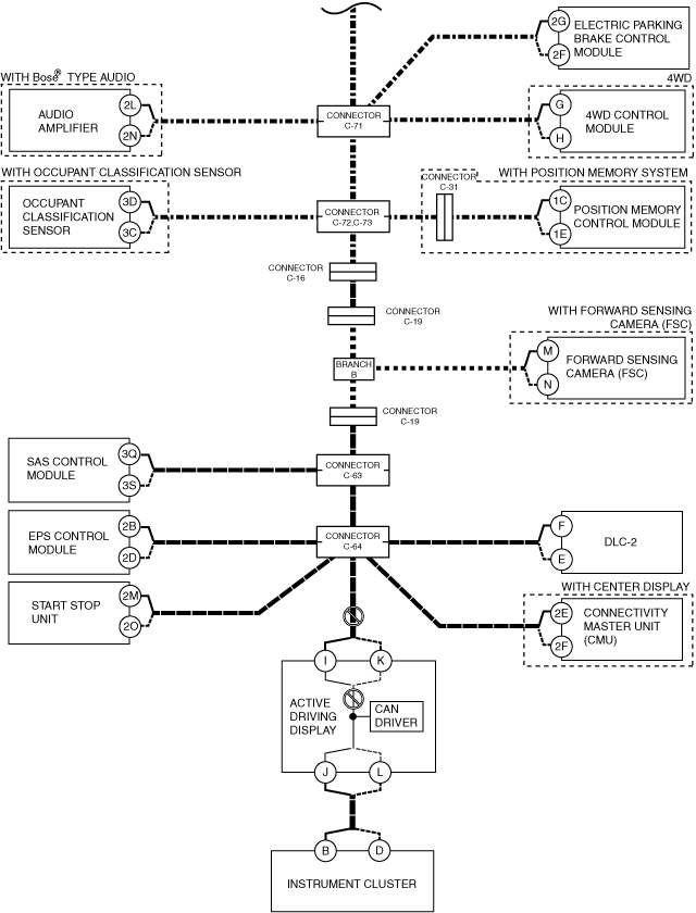
HUD*10
(Active driving display)
|
U0100:00
|
×
|
|
|
×
|
|
×
|
|
×
|
|
×
|
|
×
|
|
|
×
|
|
|
|
×
|
|
×
|
|
×
|
|
×
|
|
|
|
|
|
|
|
U0101:00
|
|
|
|
|
×
|
×
|
|
×
|
|
×
|
|
×
|
|
|
×
|
|
|
|
×
|
|
×
|
|
×
|
|
×
|
|
|
|
|
|
|
|
U0104:00
|
|
|
×
|
×
|
|
×
|
|
×
|
|
×
|
|
×
|
|
|
×
|
|
|
|
×
|
|
×
|
|
×
|
|
×
|
|
|
|
|
|
|
|
U0155:00
|
|
|
|
|
|
|
|
|
|
|
|
|
|
|
|
|
|
|
|
|
|
|
|
|
|
|
|
|
|
|
×
|
|
U0156:00
|
|
|
|
|
|
|
|
|
|
|
|
|
|
|
|
|
|
|
|
|
|
|
|
|
|
|
|
×
|
|
|
|
|
U023A:00
|
|
|
|
|
|
|
|
|
|
|
|
|
|
|
|
|
|
|
|
|
|
×
|
×
|
|
×
|
|
|
|
|
|
|
|
IC
(Instrument cluster)
|
U0100:00
|
×
|
|
|
×
|
|
×
|
|
×
|
|
×
|
|
×
|
|
|
×
|
|
|
|
×
|
|
×
|
|
×
|
|
×
|
|
|
|
|
|
|
|
U0101:00
|
|
|
|
|
×
|
×
|
|
×
|
|
×
|
|
×
|
|
|
×
|
|
|
|
×
|
|
×
|
|
×
|
|
×
|
|
|
|
|
|
|
|
U0104:00
|
|
|
×
|
×
|
|
×
|
|
×
|
|
×
|
|
×
|
|
|
×
|
|
|
|
×
|
|
×
|
|
×
|
|
×
|
|
|
|
|
|
|
|
U0114:00
|
|
|
|
|
|
|
|
|
|
|
|
|
|
|
|
|
|
×
|
×
|
|
×
|
|
×
|
|
×
|
|
|
|
|
|
|
|
U0121:00
|
|
×
|
|
×
|
|
×
|
|
×
|
|
×
|
|
×
|
|
|
×
|
|
|
|
×
|
|
×
|
|
×
|
|
×
|
|
|
|
|
|
|
|
U0128:00
|
|
|
|
|
|
|
|
|
|
|
|
|
|
|
|
|
×
|
|
×
|
|
×
|
|
×
|
|
×
|
|
|
|
|
|
|
|
U0131:00
|
|
|
|
|
|
|
|
|
|
|
|
|
|
|
|
|
|
|
|
|
|
|
|
|
|
×
|
|
|
|
|
|
|
U0140:00
|
|
|
|
|
|
|
×
|
×
|
|
×
|
|
×
|
|
|
×
|
|
|
|
×
|
|
×
|
|
×
|
|
×
|
|
|
|
|
|
|
|
U0151:00
|
|
|
|
|
|
|
|
|
|
|
|
|
|
|
|
|
|
|
|
|
|
|
|
×
|
×
|
|
|
|
|
|
|
|
U0156:00
|
|
|
|
|
|
|
|
|
|
|
|
|
|
|
|
|
|
|
|
|
|
|
|
|
|
|
|
×
|
|
|
|
|
U0158:00
|
|
|
|
|
|
|
|
|
|
|
|
|
|
|
|
|
|
|
|
|
|
|
|
|
|
|
|
|
|
×
|
|
|
U0182:00
|
|
|
|
|
|
|
|
|
×
|
×
|
|
×
|
|
|
×
|
|
|
|
×
|
|
×
|
|
×
|
|
×
|
|
|
|
|
|
|
|
U0214:00
|
|
|
|
|
|
|
|
|
|
|
|
|
|
|
|
|
|
|
|
|
|
|
|
|
|
|
×
|
|
|
|
|
|
U0235:00
|
|
|
|
|
|
|
|
|
|
|
|
|
|
|
|
|
|
|
|
|
|
×
|
×
|
|
×
|
|
|
|
|
|
|
|
U023A:00
|
|
|
|
|
|
|
|
|
|
|
|
|
|
|
|
|
|
|
|
|
|
×
|
×
|
|
×
|
|
|
|
|
|
|
|
M-MDS display module
|
[Fail] display pattern
|
|
PCM
|
×
|
|
|
×
|
|
×
|
|
×
|
|
×
|
|
×
|
|
|
×
|
|
|
|
×
|
|
×
|
|
×
|
|
×
|
|
|
|
|
|
|
|
ABS
|
|
×
|
|
×
|
|
×
|
|
×
|
|
×
|
|
×
|
|
|
×
|
|
|
|
×
|
|
×
|
|
×
|
|
×
|
|
|
|
|
|
|
|
SBS/MRCC*1
|
|
|
×
|
×
|
|
×
|
|
×
|
|
×
|
|
×
|
|
|
×
|
|
|
|
×
|
|
×
|
|
×
|
|
×
|
|
|
|
|
|
|
|
TCM*2
|
|
|
|
|
×
|
×
|
|
×
|
|
×
|
|
×
|
|
|
×
|
|
|
|
×
|
|
×
|
|
×
|
|
×
|
|
|
|
|
|
|
|
F_BCM
|
|
|
|
|
|
|
×
|
×
|
|
×
|
|
×
|
|
|
×
|
|
|
|
×
|
|
×
|
|
×
|
|
×
|
|
|
|
|
|
|
|
AFS/ALM
|
|
|
|
|
|
|
|
|
×
|
×
|
|
×
|
|
|
×
|
|
|
|
×
|
|
×
|
|
×
|
|
×
|
|
|
|
|
|
|
|
PLG*3
|
|
|
|
|
|
|
|
|
|
|
×
|
×
|
|
|
×
|
|
|
|
×
|
|
×
|
|
×
|
|
×
|
|
|
|
|
|
|
|
SCR*4
|
|
|
|
|
|
|
|
|
|
|
|
|
|
×
|
×
|
|
|
|
×
|
|
×
|
|
×
|
|
×
|
|
|
|
|
|
|
|
AM*5
|
|
|
|
|
|
|
|
|
|
|
|
|
|
|
|
×
|
|
|
×
|
|
×
|
|
×
|
|
×
|
|
|
|
|
|
|
|
EPB
|
|
|
|
|
|
|
|
|
|
|
|
|
|
|
|
|
×
|
|
×
|
|
×
|
|
×
|
|
×
|
|
|
|
|
|
|
|
4×4*6
|
|
|
|
|
|
|
|
|
|
|
|
|
|
|
|
|
|
×
|
×
|
|
×
|
|
×
|
|
×
|
|
|
|
|
|
|
|
DSM*7
|
|
|
|
|
|
|
|
|
|
|
|
|
|
|
|
|
|
|
|
×
|
×
|
|
×
|
|
×
|
|
|
|
|
|
|
|
FSC*8
|
|
|
|
|
|
|
|
|
|
|
|
|
|
|
|
|
|
|
|
|
|
×
|
×
|
|
×
|
|
|
|
|
|
|
|
RCM
|
|
|
|
|
|
|
|
|
|
|
|
|
|
|
|
|
|
|
|
|
|
|
|
×
|
×
|
|
|
|
|
|
|
|
EPS
|
|
|
|
|
|
|
|
|
|
|
|
|
|
|
|
|
|
|
|
|
|
|
|
|
|
×
|
|
|
|
|
|
|
SSU
|
|
|
|
|
|
|
|
|
|
|
|
|
|
|
|
|
|
|
|
|
|
|
|
|
|
|
×
|
|
|
|
|
|
CMU*9
|
|
|
|
|
|
|
|
|
|
|
|
|
|
|
|
|
|
|
|
|
|
|
|
|
|
|
|
×
|
|
|
|
|
HUD*10
|
|
|
|
|
|
|
|
|
|
|
|
|
|
|
|
|
|
|
|
|
|
|
|
|
|
|
|
|
×
|
×
|
|
|
IC
|
|
|
|
|
|
|
|
|
|
|
|
|
|
|
|
|
|
|
|
|
|
|
|
|
|
|
|
|
×
|
|
×
|
|
Diagnostic result
|
|
Possible cause and inspection item
|
|
|
|
|
|
|
|
|
|
|
|
|
|
|
|
|
|
|
|
|
|
|
|
|
|
|
|
|
|
|
|
*1 :With Mazda Radar Cruise Control (MRCC) system
*2 :ATX
*3 :With power liftgate (PLG) system
*4 :With SCR system
*5 :With Bose® type audio
*6 :4WD
*7 :With position memory system
*8 :With forward sensing camera (FSC)
*9 :With center display
*10 :With active driving display
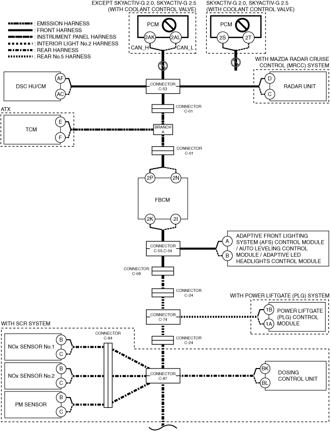
A
Possible cause
-
• Connector terminal disconnection, poor contact, damage, deformation, corrosion
• PCM power supply voltage or body ground malfunction
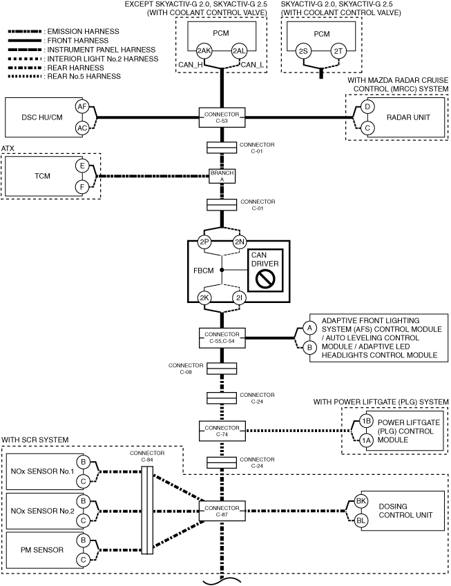
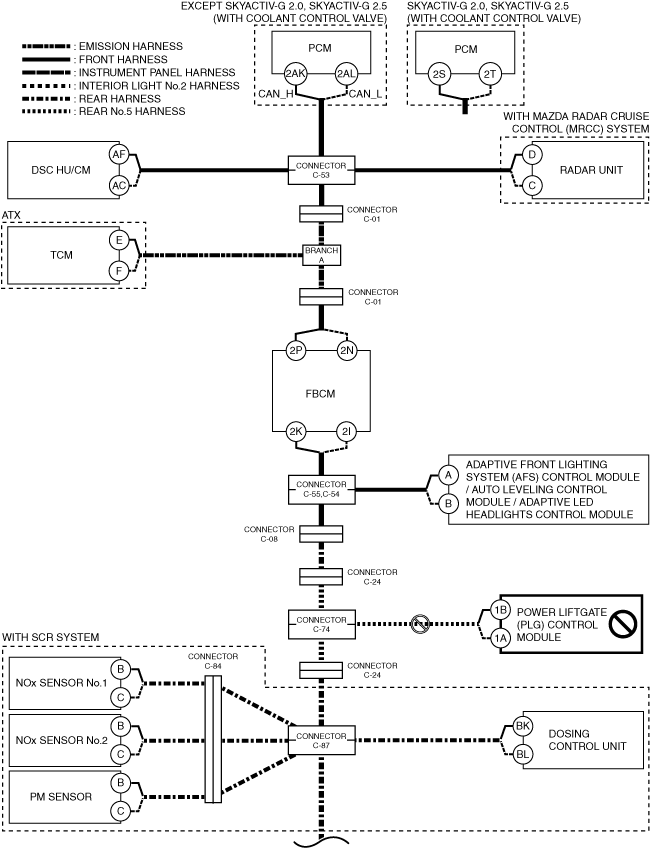
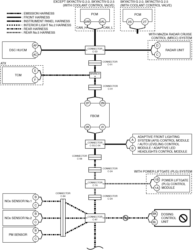
• Open circuit in wiring harness between PCM and connector C-53
• Connector C-53 malfunction
• PCM malfunction
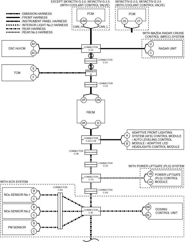
System wiring diagram
Inspection item
-
• PCM power supply voltage-related wiring harness and fuse
• PCM body ground related wiring harness
• PCM connector
• Connector C-53
• Wiring harness between PCM terminal 2AK and connector C-53 (except SKYACTIV-G 2.0, SKYACTIV-G 2.5 with coolant control valve))
• Wiring harness between PCM terminal 2AL and connector C-53 (except SKYACTIV-G 2.0, SKYACTIV-G 2.5 with coolant control valve))
• Wiring harness between PCM terminal 2S and connector C-53 (SKYACTIV-G 2.0, SKYACTIV-G 2.5 with coolant control valve))
• Wiring harness between PCM terminal 2T and connector C-53 (SKYACTIV-G 2.0, SKYACTIV-G 2.5 with coolant control valve))
• PCM
B
Possible cause
-
• Connector terminal disconnection, poor contact, damage, deformation, corrosion
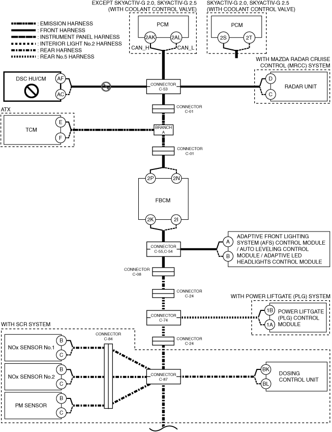
• DSC HU/CM power supply voltage or body ground malfunction
• Open circuit in wiring harness between DSC HU/CM and connector C-53
• Connector C-53 malfunction
• DSC HU/CM malfunction
System wiring diagram
Inspection item
-
• DSC HU/CM power supply voltage-related wiring harness and fuse
• DSC HU/CM body ground related wiring harness
• DSC HU/CM connector
• Connector C-53
• Wiring harness between DSC HU/CM terminal AF and connector C-53
• Wiring harness between DSC HU/CM terminal AC and connector C-53
• DSC HU/CM
C
Possible cause
-
• Connector terminal disconnection, poor contact, damage, deformation, corrosion
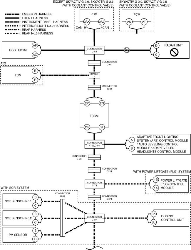
• Radar unit power supply voltage or body ground malfunction
• Open circuit in wiring harness between radar unit and connector C-53
• Connector C-53 malfunction
• Radar unit malfunction
System wiring diagram
Inspection item
-
• Radar unit power supply voltage-related wiring harness and fuse
• Radar unit body ground related wiring harness
• Radar unit connector
• Connector C-53
• Wiring harness between radar unit terminal D and connector C-53
• Wiring harness between radar unit terminal C and connector C-53
• Radar unit
D
ATX
-
Possible cause
-
• Connector terminal disconnection, poor contact, damage, deformation, corrosion
• Open circuit in wiring harness between connector C-53 and connector C-01
• Open circuit in wiring harness between connector C-01 and branch A
• Connector C-53 malfunction
• Connector C-01 malfunction
System wiring diagram
-
Inspection item
-
• Connector C-53
• Connector C-01
• Wiring harness between connector C-53 and connector C-01
• Wiring harness between connector C-01 and branch A
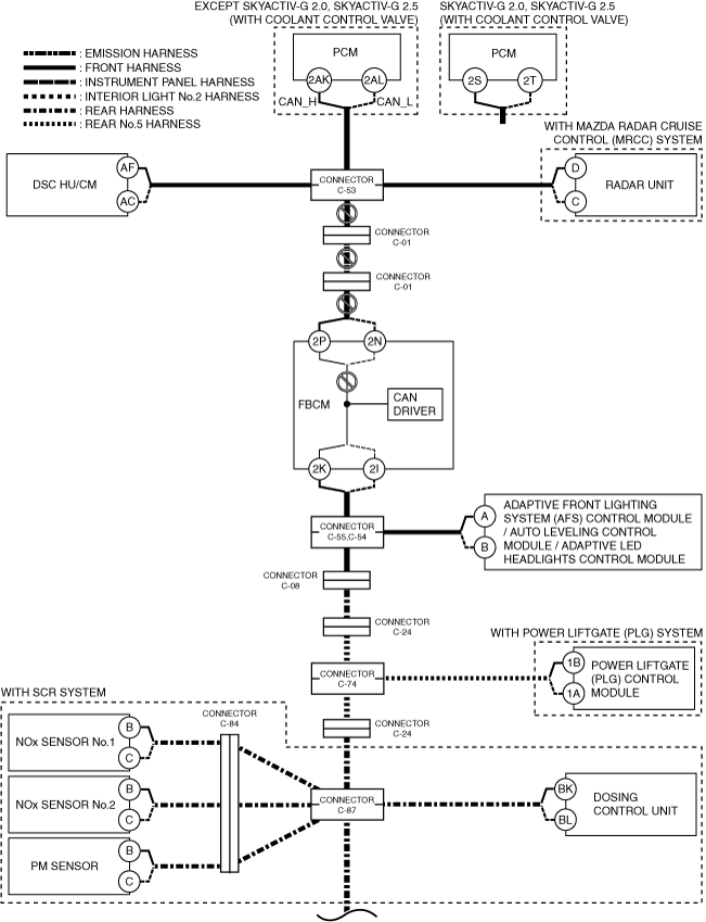
MTX
-
Possible cause
-
• Connector terminal disconnection, poor contact, damage, deformation, corrosion
• Open circuit in wiring harness between connector C-53 and connector C-01
• Open circuit in wiring harness between connector C-01 and connector C-01
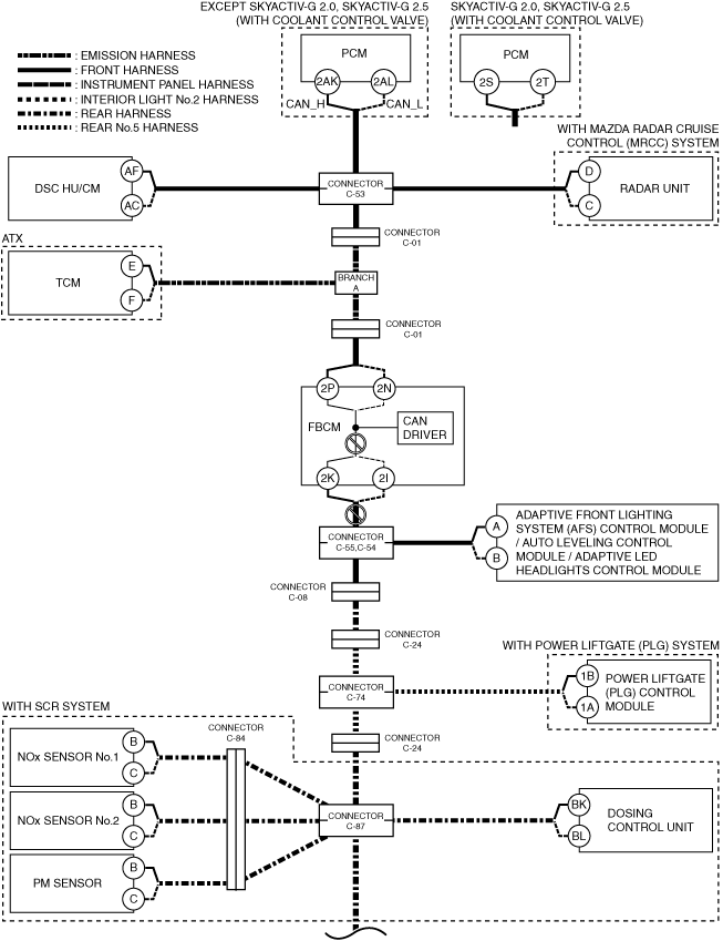
• Open circuit in wiring harness between connector C-01 and front body control module (FBCM)
• Connector C-53 malfunction
• Connector C-01 malfunction
• CAN circuit in front body control module (FBCM) malfunction
System wiring diagram
-
Inspection item
-
• Front body control module (FBCM) connector
• Connector C-53
• Connector C-01
• Wiring harness between connector C-53 and connector C-01
• Wiring harness between connector C-01 and connector C-01
• Wiring harness between front body control module (FBCM) terminal 2P and connector C-01
• Wiring harness between front body control module (FBCM) terminal 2N and connector C-01
• Front body control module (FBCM)
-
― Between front body control module (FBCM) terminal 2P and front body control module (FBCM) terminal 2K
― Between front body control module (FBCM) terminal 2N and front body control module (FBCM) terminal 2I
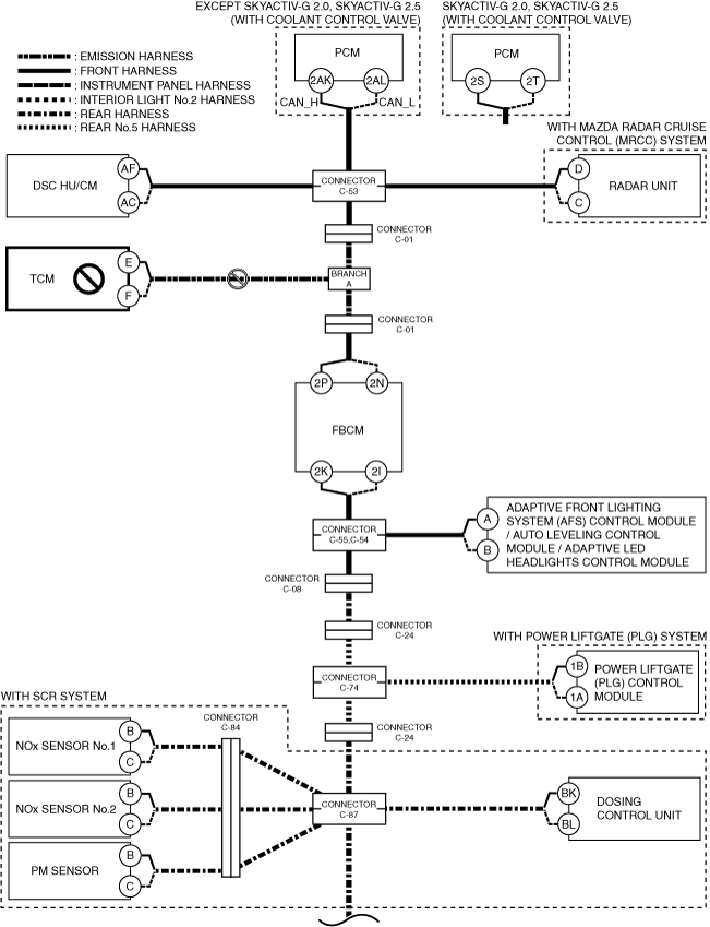
E
Possible cause
-
• Connector terminal disconnection, poor contact, damage, deformation, corrosion
• TCM power supply voltage or body ground malfunction
• Open circuit in wiring harness between TCM and branch A
• TCM malfunction
System wiring diagram
Inspection item
-
• TCM power supply voltage-related wiring harness and fuse
• TCM body ground related wiring harness
• TCM connector
• Wiring harness between TCM terminal E and branch A
• Wiring harness between TCM terminal F and branch A
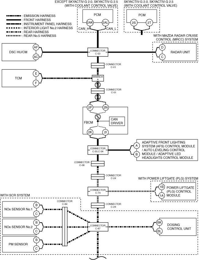
F
Possible cause
-
• Connector terminal disconnection, poor contact, damage, deformation, corrosion
• Open circuit in wiring harness between branch A and connector C-01
• Open circuit in wiring harness between front body control module (FBCM) and connector C-01
• Connector C-01 malfunction
• CAN circuit in front body control module (FBCM) malfunction
System wiring diagram
Inspection item
-
• Front body control module (FBCM) connector
• Connector C-01
• Wiring harness between branch A and connector C-01
• Wiring harness between front body control module (FBCM) terminal 2P and connector C-01
• Wiring harness between front body control module (FBCM) terminal 2N and connector C-01
• Front body control module (FBCM)
-
― Between front body control module (FBCM) terminal 2P and front body control module (FBCM) terminal 2K
― Between front body control module (FBCM) terminal 2N and front body control module (FBCM) terminal 2I
G
Possible cause
-
• Connector terminal disconnection, poor contact, damage, deformation, corrosion
• Front body control module (FBCM) power supply voltage or body ground malfunction
• Front body control module (FBCM) malfunction
System wiring diagram
Inspection item
-
• Front body control module (FBCM) power supply voltage-related wiring harness and fuse
• Front body control module (FBCM) body ground related wiring harness
• Front body control module (FBCM)
H
Possible cause
-
• Connector terminal disconnection, poor contact, damage, deformation, corrosion
• Open circuit in wiring harness between front body control module (FBCM) and connectors C-55,C-54
• Connectors C-55,C-54 malfunction
• CAN circuit in front body control module (FBCM) malfunction
System wiring diagram
Inspection item
-
• Front body control module (FBCM) connector
• Connectors C-55,C-54
• Wiring harness between front body control module (FBCM) terminal 2K and connector C-55
• Wiring harness between front body control module (FBCM) terminal 2I and connector C-54
• Front body control module (FBCM)
-
― Between front body control module (FBCM) terminal 2P and front body control module (FBCM) terminal 2K
― Between front body control module (FBCM) terminal 2N and front body control module (FBCM) terminal 2I
I
Possible cause
-
• Connector terminal disconnection, poor contact, damage, deformation, corrosion
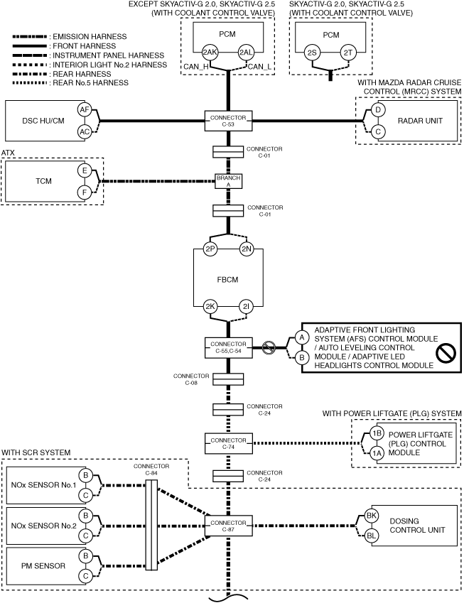
• Adaptive front lighting system (AFS) control module / auto leveling control module / adaptive LED headlights control module power supply voltage or body ground malfunction
• Open circuit in wiring harness between adaptive front lighting system (AFS) control module / auto leveling control module / adaptive LED headlights control module and connectors C-55,C-54
• Connectors C-55,C-54 malfunction
• Adaptive front lighting system (AFS) control module / auto leveling control module / adaptive LED headlights control module malfunction
System wiring diagram
Inspection item
-
• Adaptive front lighting system (AFS) control module / auto leveling control module / adaptive LED headlights control module power supply voltage-related wiring harness and fuse
• Adaptive front lighting system (AFS) control module / auto leveling control module / adaptive LED headlights control module body ground related wiring harness
• Adaptive front lighting system (AFS) control module / auto leveling control module / adaptive LED headlights control module connector
• Connectors C-55,C-54
• Wiring harness between adaptive front lighting system (AFS) control module / auto leveling control module / adaptive LED headlights control module terminal A and connector C-55
• Wiring harness between adaptive front lighting system (AFS) control module / auto leveling control module / adaptive LED headlights control module terminal B and connector C-54
• Adaptive front lighting system (AFS) control module / auto leveling control module / adaptive LED headlights control module
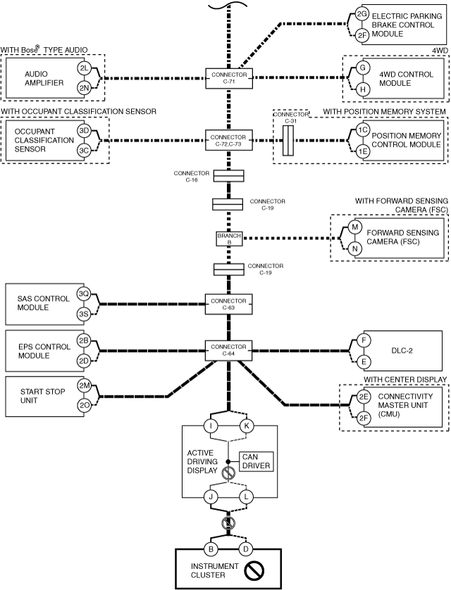
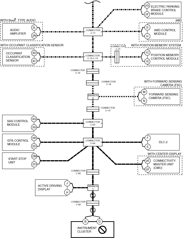
J
Possible cause
-
• Connector terminal disconnection, poor contact, damage, deformation, corrosion
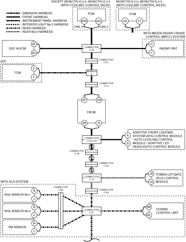
• Open circuit in wiring harness between connectors C-55,C-54 and connector C-08
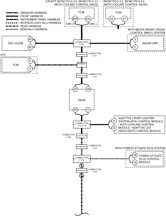
• Open circuit in wiring harness between connector C-08 and connector C-24
• Open circuit in wiring harness between connector C-24 and connector C-74
• Connectors C-55, C-54 malfunction
• Connector C-08 malfunction
• Connector C-24 malfunction
• Connector C-74 malfunction
System wiring diagram
Inspection item
-
• Wiring harness between connectors C-55,C-54 and connector C-08
• Wiring harness between connector C-08 and connector C-24
• Wiring harness between connector C-24 and connector C-74
• Connectors C-55, C-54
• Connector C-08
• Connector C-24
• Connector C-74
K
Possible cause
-
• Connector terminal disconnection, poor contact, damage, deformation, corrosion
• Power liftgate (PLG) control module power supply voltage or body ground malfunction
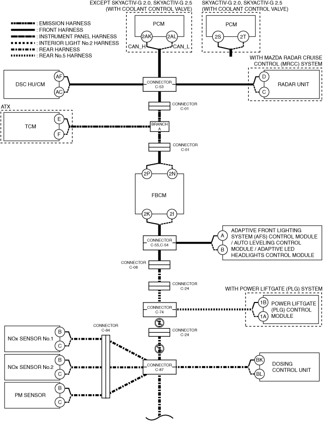
• Open circuit in wiring harness between power liftgate (PLG) control module and connector C-74
• Connector C-74 malfunction
• Power liftgate (PLG) control module malfunction
System wiring diagram
Inspection item
-
• Power liftgate (PLG) control module power supply voltage-related wiring harness and fuse
• Power liftgate (PLG) control module body ground related wiring harness
• Power liftgate (PLG) control module connector
• Connector C-74
• Wiring harness between power liftgate (PLG) control module terminal 1B and connector C-74
• Wiring harness between power liftgate (PLG) control module terminal 1A and connector C-74
• Power liftgate (PLG) control module
L
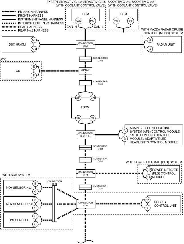
With SCR system
-
Possible cause
-
• Connector terminal disconnection, poor contact, damage, deformation, corrosion
• Open circuit in wiring harness between connector C-74 and connector C-24
• Open circuit in wiring harness between connector C-24 and connector C-87
• Connector C-74 malfunction
• Connector C-24 malfunction
• Connector C-87 malfunction
System wiring diagram
-
Inspection item
-
• Wiring harness between connector C-74 and connector C-24
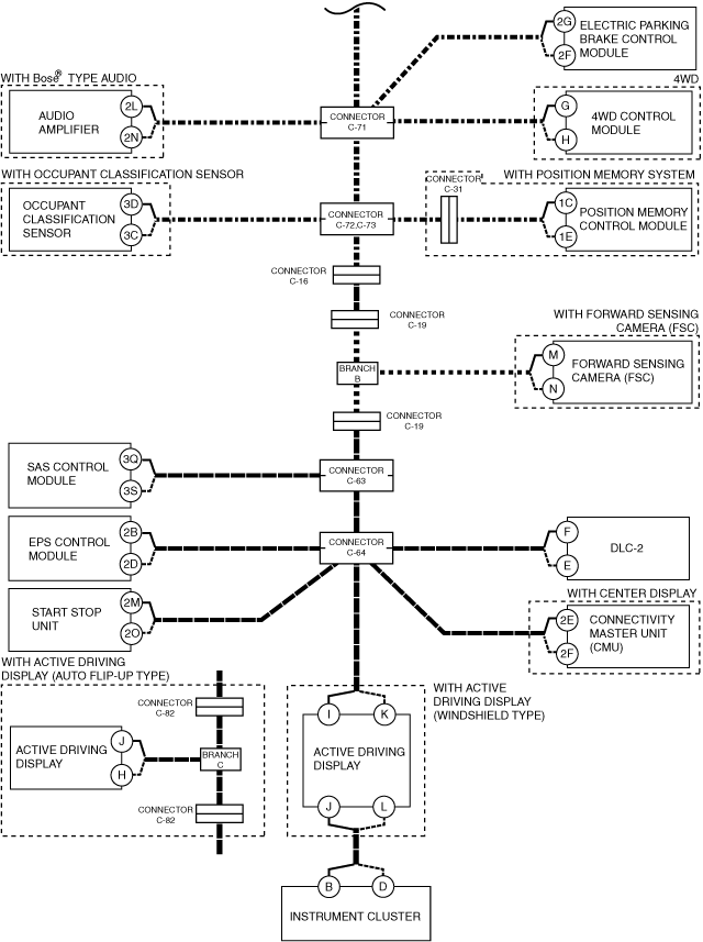
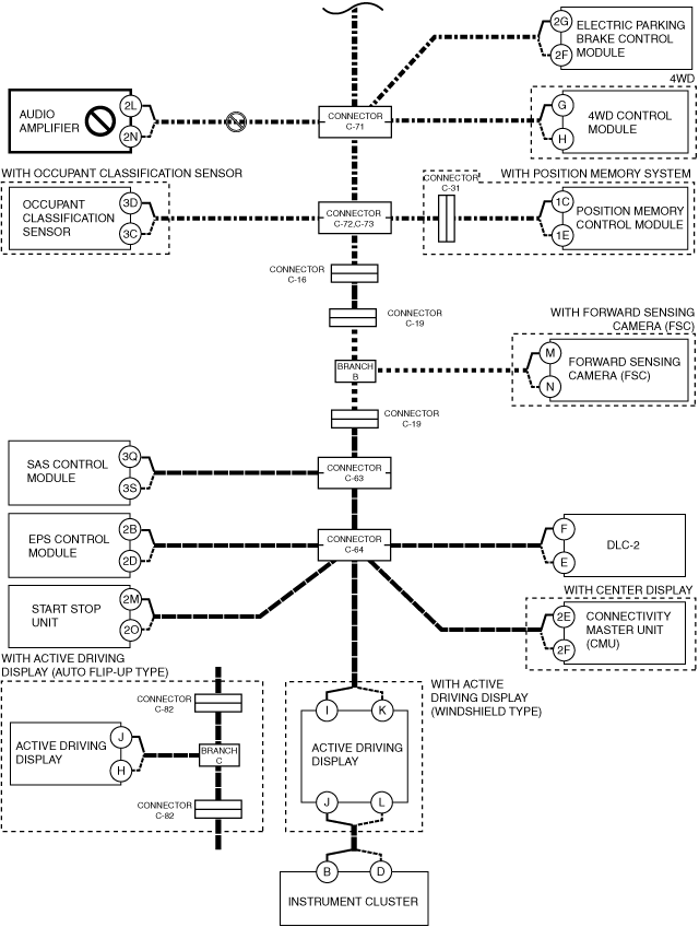
• Wiring harness between connector C-24 and connector C-71
• Connector C-74
• Connector C-24
• Connector C-71
Without SCR system
-
Possible cause
-
• Connector terminal disconnection, poor contact, damage, deformation, corrosion
• Open circuit in wiring harness between connector C-74 and connector C-24
• Open circuit in wiring harness between connector C-24 and connector C-71
• Connector C-74 malfunction
• Connector C-24 malfunction
• Connector C-71 malfunction
System wiring diagram
-
Inspection item
-
• Wiring harness between connector C-74 and connector C-24
• Wiring harness between connector C-24 and connector C-71
• Connector C-74
• Connector C-24
• Connector C-71
M
Possible cause
-
• Connector terminal disconnection, poor contact, damage, deformation, corrosion
• NOx sensor No.1 power supply voltage or body ground malfunction
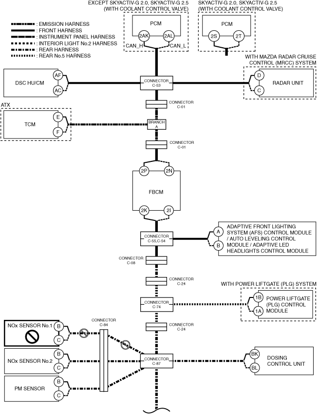
• Open circuit in wiring harness between NOx sensor No.1 and connector C-84
• Open circuit in wiring harness between connector C-84 and connector C-87
• Connector C-84 malfunction
• Connector C-87 malfunction
• NOx sensor No.1 malfunction
System wiring diagram
Inspection item
-
• NOx sensor No.1 power supply voltage-related wiring harness and fuse
• NOx sensor No.1 body ground related wiring harness
• NOx sensor No.1 connector
• Connector C-84
• Connector C-87
• Wiring harness between NOx sensor No.1 terminal B and connector C-84
• Wiring harness between NOx sensor No.1 terminal C and connector C-84
• Wiring harness between connector C-84 and connector C-87
• NOx sensor No.1
N
Possible cause
-
• Connector terminal disconnection, poor contact, damage, deformation, corrosion
• Dosing control unit power supply voltage or body ground malfunction
• Open circuit in wiring harness between dosing control unit and connector C-87
• Connector C-87 malfunction
• Dosing control unit malfunction
System wiring diagram
Inspection item
-
• Dosing control unit power supply voltage-related wiring harness and fuse
• Dosing control unit body ground related wiring harness
• Dosing control unit connector
• Connector C-87
• Wiring harness between dosing control unit terminal BK and connector C-87
• Wiring harness between dosing control unit terminal BL and connector C-87
• Dosing control unit
O
Possible cause
-
• Connector terminal disconnection, poor contact, damage, deformation, corrosion
• Open circuit in wiring harness between connector C-87 and connector C-71
• Connector C-87 malfunction
• Connector C-71 malfunction
System wiring diagram
Inspection item
-
• Connector C-87
• Connector C-71
• Wiring harness between connector C-87 and connector C-71
P
Possible cause
-
• Connector terminal disconnection, poor contact, damage, deformation, corrosion
• Audio amplifier power supply voltage or body ground malfunction
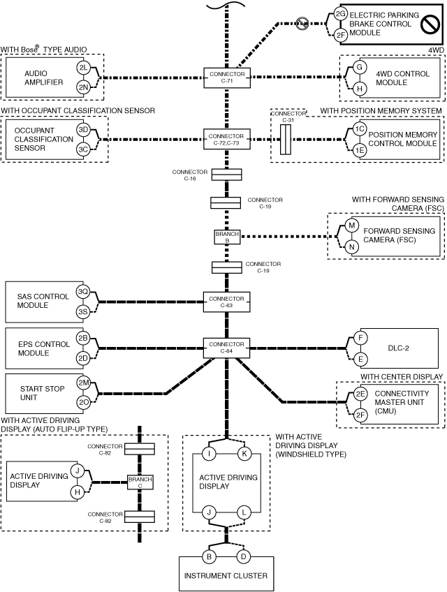
• Open circuit in wiring harness between audio amplifier and connector C-71
• Connector C-71 malfunction
• Audio amplifier malfunction
System wiring diagram
Inspection item
-
• Audio amplifier power supply voltage-related wiring harness and fuse
• Audio amplifier body ground related wiring harness
• Audio amplifier connector
• Connector C-71
• Wiring harness between audio amplifier terminal 2L and connector C-71
• Wiring harness between audio amplifier terminal 2N and connector C-71
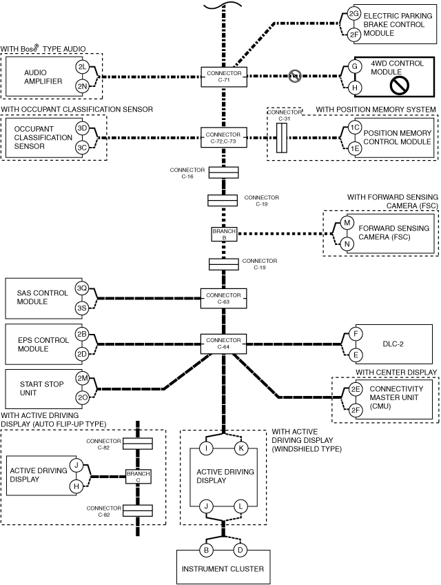
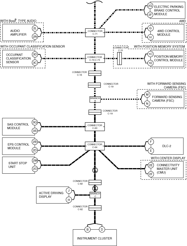
• Audio amplifier
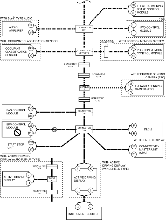
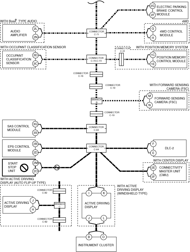
Q
Possible cause
-
• Connector terminal disconnection, poor contact, damage, deformation, corrosion
• Electric parking brake control module power supply voltage or body ground malfunction
• Open circuit in wiring harness between electric parking brake control module and connector C-71
• Connector C-71 malfunction
• Electric parking brake control module malfunction
System wiring diagram
Inspection item
-
• Electric parking brake control module power supply voltage-related wiring harness and fuse
• Electric parking brake control module body ground related wiring harness
• Electric parking brake control module connector
• Connector C-71
• Wiring harness between electric parking brake control module terminal 2G and connector C-71
• Wiring harness between electric parking brake control module terminal 2F and connector C-71
• Electric parking brake control module
R
Possible cause
-
• Connector terminal disconnection, poor contact, damage, deformation, corrosion
• 4WD control module power supply voltage or body ground malfunction
• Open circuit in wiring harness between 4WD control module and connector C-71
• Connector C-71 malfunction
• 4WD control module malfunction
System wiring diagram
Inspection item
-
• 4WD control module power supply voltage-related wiring harness and fuse
• 4WD control module body ground related wiring harness
• 4WD control module connector
• Connector C-71
• Wiring harness between 4WD control module terminal G and connector C-71
• Wiring harness between 4WD control module terminal H and connector C-71
• 4WD control module
S
Possible cause
-
• Connector terminal disconnection, poor contact, damage, deformation, corrosion
• Open circuit in wiring harness between connector C-71 and connectors C-72, C-73
• Connector C-71 malfunction
• Connectors C-72, C-73 malfunction
System wiring diagram
Inspection item
-
• Connector C-71
• Connectors C-72, C-73
• Wiring harness between connector C-71 and connectors C-72, C-73
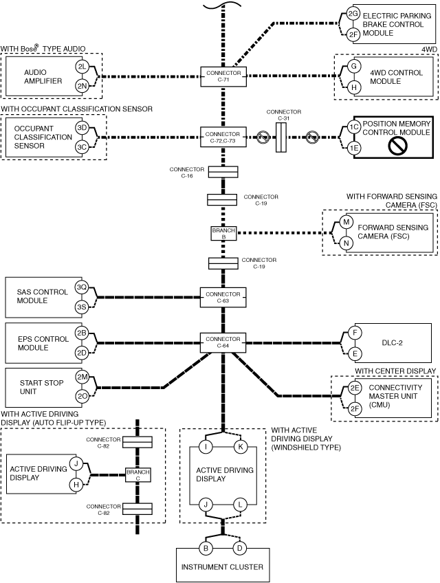
T
Possible cause
-
• Connector terminal disconnection, poor contact, damage, deformation, corrosion
• Position memory control module power supply voltage or body ground malfunction
• Open circuit in wiring harness between position memory control module and connector C-31
• Open circuit in wiring harness between connector C-31 and connectors C-72, C-73
• Connector C-31 malfunction
• Connectors C-72, C-73 malfunction
• Position memory control module malfunction
System wiring diagram
Inspection item
-
• Position memory control module power supply voltage-related wiring harness and fuse
• Position memory control module body ground related wiring harness
• Position memory control module connector
• Connector C-31
• Connectors C-72, C-73
• Wiring harness between position memory control module terminal 1C and connector C-31
• Wiring harness between position memory control module terminal 1E and connector C-31
• Wiring harness between connector C-31 and connectors C-72, C-73
• Position memory control module
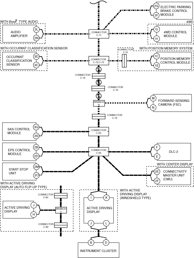
U
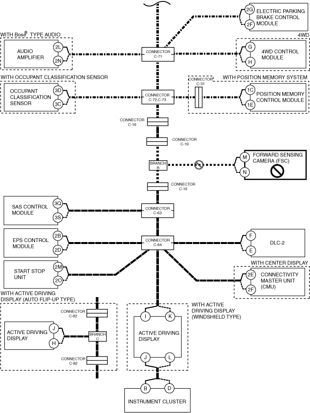
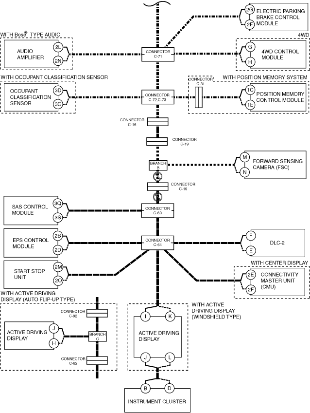
With forward sensing camera (FSC)
-
Possible cause
-
• Connector terminal disconnection, poor contact, damage, deformation, corrosion
• Open circuit in wiring harness between connectors C-72, C-73 and connector C-16
• Open circuit in wiring harness between connector C-16 and connector C-19
• Open circuit in wiring harness between connector C-19 and branch B
• Connectors C-72, C-73 malfunction
• Connector C-16 malfunction
• Connector C-19 malfunction
System wiring diagram
-
Inspection item
-
• Connectors C-72, C-73
• Connector C-16
• Connector C-19
• Wiring harness between connectors C-72, C-73 and connector C-16
• Wiring harness between connector C-16 and connector C-19
• Wiring harness between connector C-19 and branch B
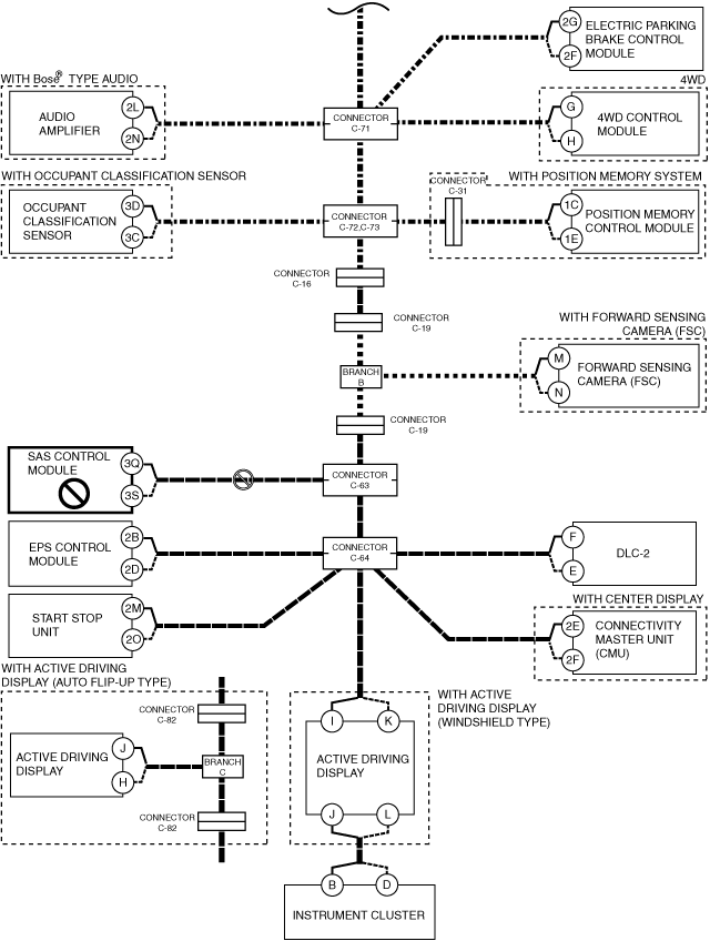
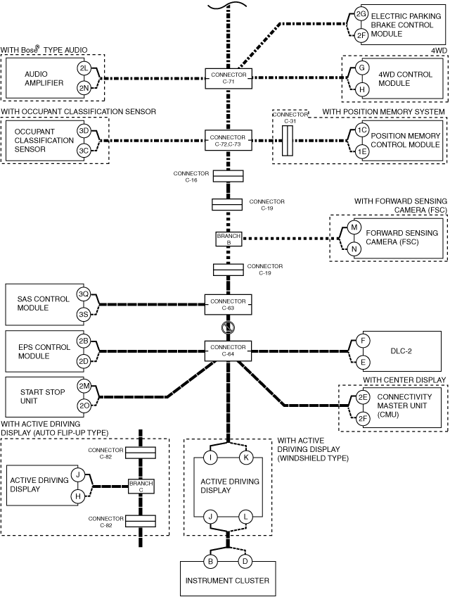
Without forward sensing camera (FSC)
-
Possible cause
-
• Connector terminal disconnection, poor contact, damage, deformation, corrosion
• Open circuit in wiring harness between connectors C-72, C-73 and connector C-16
• Open circuit in wiring harness between connector C-16 and connector C-19
• Open circuit in wiring harness between connector C-19 and connector C-19
• Open circuit in wiring harness between connector C-19 and connector C-63
• Connectors C-72, C-73 malfunction
• Connector C-16 malfunction
• Connector C-19 malfunction
• Connector C-63 malfunction
System wiring diagram
-
Inspection item
-
• Connectors C-72, C-73
• Connector C-16
• Connector C-19
• Connector C-63
• Wiring harness between connectors C-72, C-73 and connector C-16
• Wiring harness between connector C-16 and connector C-19
• Wiring harness between connector C-19 and connector C-19
• Wiring harness between connector C-19 and connector C-63
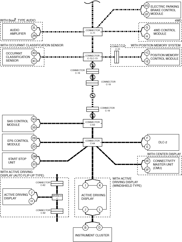
V
Possible cause
-
• Connector terminal disconnection, poor contact, damage, deformation, corrosion
• Forward sensing camera (FSC) power supply voltage or body ground malfunction
• Open circuit in wiring harness between forward sensing camera (FSC) and branch B
• Forward sensing camera (FSC) malfunction
System wiring diagram
Inspection item
-
• Forward sensing camera (FSC) power supply voltage-related wiring harness and fuse
• Forward sensing camera (FSC) body ground related wiring harness
• Forward sensing camera (FSC) connector
• Wiring harness between forward sensing camera (FSC) terminal M and branch B
• Wiring harness between forward sensing camera (FSC) terminal N and branch B
• Forward sensing camera (FSC)
W
Possible cause
-
• Connector terminal disconnection, poor contact, damage, deformation, corrosion
• Open circuit in wiring harness between branch B and connector C-19
• Open circuit in wiring harness between connector C-19 and connector C-63
• Connector C-19 malfunction
• Connector C-63 malfunction
System wiring diagram
Inspection item
-
• Connector C-19
• Connector C-63
• Wiring harness between branch B and connector C-19
• Wiring harness between connector C-19 and connector C-63
X
Possible cause
-
• Connector terminal disconnection, poor contact, damage, deformation, corrosion
• SAS control module power supply voltage or body ground malfunction
• Open circuit in wiring harness between SAS control module and connector C-63
• Connector C-63 malfunction
• SAS control module malfunction
System wiring diagram
Inspection item
-
Warning
-
• Handling the component parts of the SRS air bag system improperly can accidentally operate (deploy) the air bag module, which may seriously injure you. Read the service warnings and cautions before handling the air bag system components of the SRS air bag system.
-
• SAS control module power supply voltage-related wiring harness and fuse
• SAS control module body ground related wiring harness
• SAS control module connector
• Connector C-64
• Wiring harness between SAS control module terminal 3Q and connector C-64
• Wiring harness between SAS control module terminal 3S and connector C-64
• SAS control module
Y
Possible cause
-
• Connector terminal disconnection, poor contact, damage, deformation, corrosion
• Open circuit in wiring harness between connector C-63 and connector C-64
• Connector C-63 malfunction
• Connector C-64 malfunction
System wiring diagram
Inspection item
-
• Connector C-63
• Connector C-64
• Wiring harness between connector C-63 and connector C-64
Z
Possible cause
-
• Connector terminal disconnection, poor contact, damage, deformation, corrosion
• EPS control module power supply voltage or body ground malfunction
• Open circuit in wiring harness between EPS control module and connector C-64
• Connector C-64 malfunction
• EPS control module malfunction
System wiring diagram
Inspection item
-
• EPS control module power supply voltage-related wiring harness and fuse
• EPS control module body ground related wiring harness
• EPS control module connector
• Connector C-64
• Wiring harness between EPS control module terminal 2B and connector C-64
• Wiring harness between EPS control module terminal 2D and connector C-64
• EPS control module
AA
Possible cause
-
• Connector terminal disconnection, poor contact, damage, deformation, corrosion
• Start stop unit power supply voltage or body ground malfunction
• Open circuit in wiring harness between start stop unit and connector C-64
• Connector C-64 malfunction
• Start stop unit malfunction
System wiring diagram
Inspection item
-
• Start stop unit power supply voltage-related wiring harness and fuse
• Start stop unit body ground related wiring harness
• Start stop unit connector
• Connector C-64
• Wiring harness between start stop unit terminal 2M and connector C-64
• Wiring harness between start stop unit terminal 2O and connector C-64
• Start stop unit
AB
Possible cause
-
• Connector terminal disconnection, poor contact, damage, deformation, corrosion
• Connectivity master unit (CMU) power supply voltage or body ground malfunction
• Open circuit in wiring harness between connectivity master unit (CMU) and connector C-64
• Connector C-64 malfunction
• Connectivity master unit (CMU) malfunction
System wiring diagram
Inspection item
-
• Connectivity master unit (CMU) power supply voltage-related wiring harness and fuse
• Connectivity master unit (CMU) body ground related wiring harness
• Connectivity master unit (CMU) connector
• Connector C-64
• Wiring harness between connectivity master unit (CMU) terminal 2E and connector C-64
• Wiring harness between connectivity master unit (CMU) terminal 2F and connector C-64
• Connectivity master unit (CMU)
AC
With active driving display (windshield type)
-
Possible cause
-
• Connector terminal disconnection, poor contact, damage, deformation, corrosion
• Open circuit in wiring harness between active driving display and connector C-64
• Connector C-64 malfunction
• CAN circuit in active driving display malfunction
System wiring diagram
-
Inspection item
-
• Active driving display connector
• Connector C-64
• Wiring harness between active driving display terminal I and connector C-64
• Wiring harness between active driving display terminal K and connector C-64
• Active driving display
-
― Between active driving display terminal I and active driving display terminal J
― Between active driving display terminal K and active driving display terminal L
With active driving display (auto flip-up type)
-
Possible cause
-
• Open circuit in wiring harness between connector C-64 and connector C-82
• Open circuit in wiring harness between connector C-82 and branch C
• Connector C-64 malfunction
• Connector C-82 malfunction
System wiring diagram
-
Inspection item
-
• Connector C-64
• Connector C-82
• Wiring harness between connector C-64 and connector C-82
• Wiring harness between connector C-82 and branch C
Without active driving display (windshield type) or active driving display (auto flip-up type)
-
Possible cause
-
• Connector terminal disconnection, poor contact, damage, deformation, corrosion
• Instrument cluster power supply voltage or body ground malfunction
• Open circuit in wiring harness between instrument cluster and connector C-64
• Connector C-64 malfunction
• Instrument cluster malfunction
System wiring diagram
-
Inspection item
-
• Instrument cluster power supply voltage-related wiring harness and fuse
• Instrument cluster body ground related wiring harness
• Instrument cluster connector
• Connector C-64
• Wiring harness between instrument cluster terminal B and connector C-64
• Wiring harness between instrument cluster terminal D and connector C-64
• Instrument cluster
AD
With active driving display (windshield type)
-
Possible cause
-
• Connector terminal disconnection, poor contact, damage, deformation, corrosion
• Active driving display power supply voltage or body ground malfunction
• Active driving display malfunction
System wiring diagram
-
Inspection item
-
• Active driving display power supply voltage-related wiring harness and fuse
• Active driving display body ground related wiring harness
• Active driving display
With active driving display (auto flip-up type)
-
Possible cause
-
• Connector terminal disconnection, poor contact, damage, deformation, corrosion
• Active driving display power supply voltage or body ground malfunction
• Open circuit in wiring harness between active driving display and branch C
• Active driving display malfunction
System wiring diagram
-
Inspection item
-
• Active driving display power supply voltage-related wiring harness and fuse
• Active driving display body ground related wiring harness
• Active driving display connector
• Wiring harness between active driving display terminal J and branch C
• Wiring harness between active driving display terminal H and branch C
• Active driving display
AE
With active driving display (windshield type)
-
Possible cause
-
• Connector terminal disconnection, poor contact, damage, deformation, corrosion
• Instrument cluster power supply voltage or body ground malfunction
• Open circuit in wiring harness between active driving display and instrument cluster
• Instrument cluster malfunction
• CAN circuit in active driving display malfunction
System wiring diagram
-
Inspection item
-
• Instrument cluster power supply voltage-related wiring harness and fuse
• Instrument cluster body ground related wiring harness
• Instrument cluster connector
• Active driving display connector
• Wiring harness between active driving display terminal J and instrument cluster terminal B
• Wiring harness between active driving display terminal L and instrument cluster terminal D
• Active driving display
-
― Between active driving display terminal I and active driving display terminal J
― Between active driving display terminal K and active driving display terminal L
With active driving display (auto flip-up type)
-
Possible cause
-
• Connector terminal disconnection, poor contact, damage, deformation, corrosion
• Instrument cluster power supply voltage or body ground malfunction
• Open circuit in wiring harness between branch C and connector C-82
• Open circuit in wiring harness between connector C-82 and instrument cluster
• Connector C-82 malfunction
• Instrument cluster malfunction
System wiring diagram
-
Inspection item
-
• Instrument cluster power supply voltage-related wiring harness and fuse
• Instrument cluster body ground related wiring harness
• Instrument cluster connector
• Connector C-82
• Wiring harness between branch C and connector C-82
• Wiring harness between connector C-82 and instrument cluster terminal B
• Wiring harness between connector C-82 and instrument cluster terminal D