 |
bfw4ua00000033
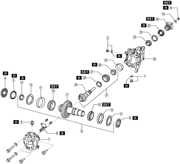
TRANSFER DISASSEMBLY
id031600000200
bfw4ua00000033
|
|
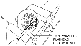
1
|
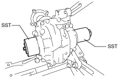
Drain plug, washer
|
|
2
|
Oil level plug, washer
|
|
3
|
Breather
|
|
4
|
Transfer oil seal (RH) No.1
|
|
5
|
Transfer oil seal (RH) No.2
|
|
6
|
Transfer oil seal (LH)
|
|
7
|
Drive gear case
|
|
8
|
Baffle plate
|
|
9
|
Ring gear shaft component
|
|
10
|
Adjustment shim (RH)
|
|
11
|
Bearing outer race (RH)
|
|
12
|
Adjustment shim (LH)
|
|
13
|
Bearing outer race (LH)
|
|
14
|
Transfer oil seal (RH) No.3
|
|
15
|
Bearing inner race (RH)
|
|
16
|
Bearing inner race (LH)
|
|
17
|
Ring gear shaft
|
|
18
|
Locknut
|
|
19
|
Washer
|
|
20
|
Companion flange component
|
|
21
|
Drive pinion gear component
|
|
22
|
Oil seal
|
|
23
|
Bearing inner race (rear)
|
|
24
|
Bearing outer race (front)
|
|
25
|
Bearing outer race (rear)
|
|
26
|
Collapsible spacer
|
|
27
|
Bearing inner race (front)
|
|
28
|
Spacer
|
|
29
|
Drive pinion gear
|
|
30
|
Front carrier
|
Transfer Component Disassembly Procedure
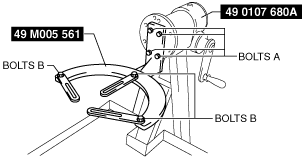
1. Assemble the SST (49 M005 561) to the SST (49 0107 680A).
bfw4ua00000006
|
2. Install the transfer component to the SST.
bfw4ua00000007
|
3. Remove the drain plug, washer.
4. Remove the oil level plug, washer.
5. Remove the breather.
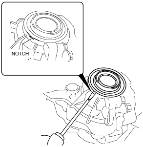
6. Insert a flathead screwdriver into the notch of the transfer and remove the oil seal (RH) No.1.
bfw4ua00000034
|
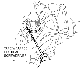
7. Insert a tape-wrapped flathead screwdriver into the lip area of the oil seal (RH) No.2 as shown in the figure and remove the oil seal (RH) No.2.
bfw4ua00000035
|
8. Insert a tape-wrapped flathead screwdriver into the lip area of the oil seal (LH) as shown in the figure and remove the oil seal (LH).
bfw4ua00000036
|
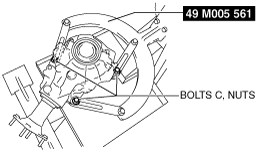
9. Install the SSTs to the transfer component as shown in the figure.
bfw4ua00000037
|
10. Tighten down the bolts on the left and right of the SST until the ring gear shaft component.
bfw4ua00000038
|
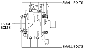
11. Remove the drive gear case installation bolts (2 large, 10 small).
bfw4ua00000008
|
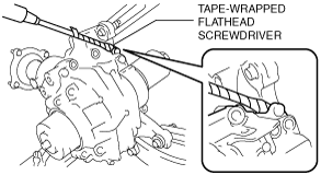
12. Remove the drive gear case using a tape-wrapped flathead screwdriver.
bfw4ua00000039
|
13. Remove the baffle plate.
bfw4ua00000010
|
14. Remove the ring gear shaft component.
bfw2za00000014
|
15. Remove the SSTs.
16. Remove the adjustment shim (RH) and bearing outer race (RH).
17. Remove the adjustment shim (LH) and bearing outer race (LH).
18. Fix the toothed part of the ring gear in a vice to secure the ring gear shaft.
19. Remove the transfer oil seal (RH) No.3 using a tape-wrapped flathead screwdriver.
bfw4ua00000012
|
20. Remove the bearing inner race (LH) using the SST.
bfw4ua00000013
|
21. Fix the toothed part of the ring gear in a vice to secure the ring gear shaft.
22. Remove the bearing inner race (RH) using the SST.
bfw3ja00000085
|
23. Secure the companion flange using the SST and remove the locknut.
bfw3ja00000086
|
24. Remove the washer.
25. Remove the companion flange component using the SST.
bfw3ja00000087
|
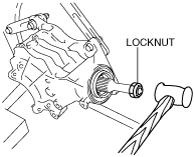
26. Install a locknut to the thread of the drive pinion gear.
bfw3ja00000088
|
27. Lightly tap the locknut with a copper hammer and remove the drive pinion gear component.
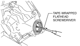
28. Remove the oil seal using a tape-wrapped flathead screwdriver.
bfw4ua00000014
|
29. Remove the bearing inner race (rear).
30. Set the brass bar to the bearing outer race (front) end surface at the notches of the front carrier in two locations. Lightly tap the end surfaces of the outer race alternately using the brass bar and hammer, and remove the bearing outer race (front).
bfw4ua00000040
|
31. Set the brass bar to the bearing outer race (rear) end surface at the notches of the front carrier in two locations. Lightly tap the end surfaces of the outer race alternately using the brass bar and hammer, and remove the bearing outer race (rear).
bfw2za00000015
|
32. Remove the collapsible spacer.
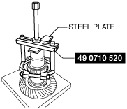
33. Remove the bearing inner race (front) using the SST and a press.
bfw3ja00000092
|
34. Remove the spacer.