 |
ac5wzw00006819
STARTER INSPECTION [SKYACTIV-G 2.0, SKYACTIV-G 2.5]
id0119i2800300
On-vehicle Inspection
1. Verify that the battery is fully charged.
2. The starter is normal if it rotates smoothly and without any noise when the engine is cranked.
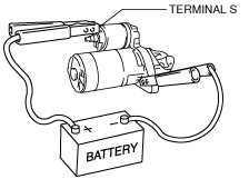
No-load Test
1. Verify that the battery is fully charged.
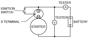
2. Connect the starter, battery, and a tester as shown in the figure.
ac5wzw00006819
|
3. Operate the starter and verify that it rotates smoothly.
4. Measure the voltage and current while the starter is operating.
Magnetic Switch Operation Inspection (Vehicle Without i-stop)
Pull-out test
1. Verify that the starter motor pinion is extended while battery positive voltage is connected to terminal S and the starter body is grounded.
ac5wzw00006820
|
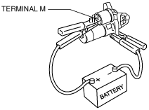
Return test
1. Disconnect the motor wire from terminal M.
2. Connect battery positive voltage to terminal M and ground the starter body.
ac5wzw00006821
|
3. Pull out the drive pinion with a screwdriver. Verify that it returns to its original position when released.
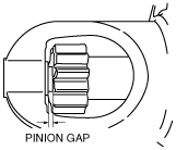
Pinion Gap Inspection (Vehicle Without i-stop)
1. Pull out the drive pinion with the battery positive voltage connected to terminal S and the starter body grounded.
ac5wzw00006820
|
2. Measure the pinion gap while the drive pinion is extended.
ac5wzw00006822
|
Starter Inner Parts Inspection (Vehicle Without i-stop)
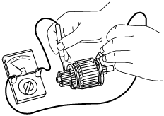
Armature
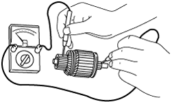
1. Verify that there is no continuity between the commutator and the core at each segment using a tester.
ac5wzw00006823
|
2. Verify that there is no continuity between the commutator and the shaft using a tester.
ac5wzw00006824
|
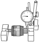
3. Place the armature on V-blocks, and measure the runout using a dial indicator.
ac5wzw00006825
|
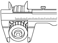
4. Measure the commutator diameter.
ac5wzw00006826
|
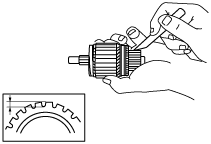
5. Measure the segment groove depth of the commutator.
ac5wzw00006827
|
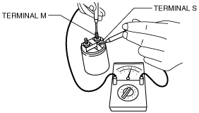
Magnetic switch
1. Inspect for continuity between terminals S and M using a tester.
ac5wzw00006828
|
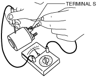
2. Inspect for continuity between terminal S and the body using a tester.
ac5wzw00006829
|
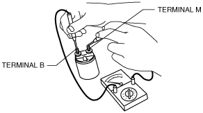
3. Verify that there is no continuity between terminals M and B using a tester.
ac5wzw00006830
|
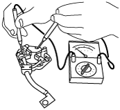
Brush and brush holder
1. Verify that there is no continuity between each insulated brush and plate using a tester.
ac5wzw00006831
|
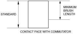
2. Measure the brush length.
ac5wzw00006832
|
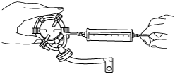
3. Measure the brush spring force using a spring balance.
ac5wzw00006833
|
am8rrw00002893
|