 |
ac5wzn00000981
ON-BOARD DIAGNOSTIC SYSTEM [DYNAMIC STABILITY CONTROL (DSC)]
id0402b2181300
OUTLINE
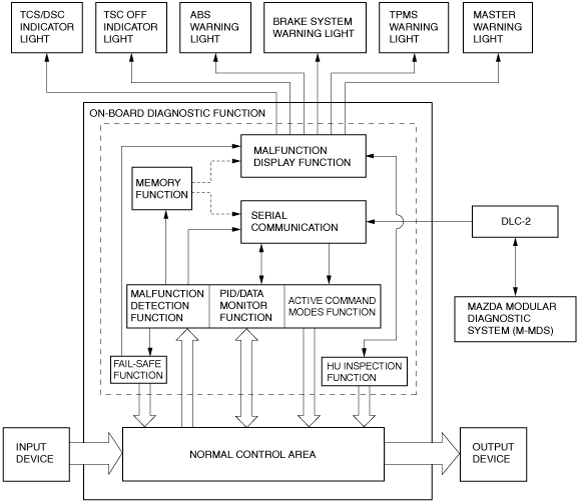
Block diagram
ac5wzn00000981
|
FUNCTION
Malfunction detection function
Memory function
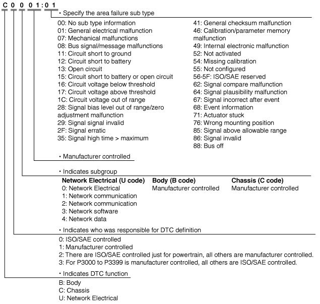
DTC 7-digit code definition
ac5wzn00001215
|
Fail-safe function
DTC table
|
DTC No. |
ABS warning light |
Brake system warning light (when parking brake is released) |
TCS/DSC indicator light |
TCS OFF indicator light |
Tire pressure monitoring system warning light |
Master warning light*1 |
Malfunction location |
Fail-safe |
Drive cycle |
Self test type*2 |
Memory function |
|---|---|---|---|---|---|---|---|---|---|---|---|
|
B10DF:46
|
-
|
-
|
Illuminated
|
-
|
-
|
Illuminated
|
DSC HU/CM (internal malfunction)
|
×
|
-
|
C, D
|
×
|
|
B11D4:08*1
|
-
|
-
|
-
|
-
|
-
|
Illuminated
|
Laser sensor
|
×
|
-
|
C, D
|
×
|
|
C0001:01
|
Illuminated
|
Illuminated
|
Illuminated
|
-
|
-
|
Illuminated
|
DSC HU/CM internal malfunction (solenoid valve system)
|
×
|
-
|
C, D
|
×
|
|
C0002:01
|
|||||||||||
|
C0003:01
|
|||||||||||
|
C0004:01
|
|||||||||||
|
C0010:01
|
|||||||||||
|
C0011:01
|
|||||||||||
|
C0014:01
|
|||||||||||
|
C0015:01
|
|||||||||||
|
C0018:01
|
|||||||||||
|
C0019:01
|
|||||||||||
|
C001C:01
|
|||||||||||
|
C001D:01
|
|||||||||||
|
C0020:11
|
Illuminated
|
-
|
Illuminated
|
-
|
-
|
Illuminated
|
Pump motor, motor relay
|
×
|
-
|
C, D
|
×
|
|
C0020:12
|
|||||||||||
|
C0020:13
|
|||||||||||
|
C0020:71
|
|||||||||||
|
C0023:62*1
|
-
|
-
|
-
|
-
|
-
|
Illuminated
|
Brake switch
|
×
|
-
|
C, D
|
×
|
|
C0030:07
|
Illuminated
|
-*3
|
Illuminated
|
-
|
Flashes*4
|
Illuminated
|
LF ABS sensor rotor
|
×
|
-
|
C, D
|
×
|
|
C0031:07
|
LF ABS wheel-speed sensor/ABS sensor rotor
|
||||||||||
|
C0031:11
|
Illuminated
|
-*3
|
Illuminated
|
-
|
Flashes*4
|
Illuminated
|
LF ABS wheel-speed sensor
|
×
|
-
|
C, D
|
×
|
|
C0031:15
|
|||||||||||
|
C0031:29
|
Illuminated
|
-*3
|
Illuminated
|
-
|
Flashes*4
|
Illuminated
|
LF ABS wheel-speed sensor/ABS sensor rotor
|
×
|
-
|
C, D
|
×
|
|
C0031:2F
|
|||||||||||
|
C0031:64
|
|||||||||||
|
C0033:07
|
Illuminated
|
-*3
|
Illuminated
|
-
|
Flashes*4
|
Illuminated
|
RF ABS sensor rotor
|
×
|
-
|
C, D
|
×
|
|
C0034:07
|
RF ABS wheel-speed sensor/ABS sensor rotor
|
||||||||||
|
C0034:11
|
Illuminated
|
-*3
|
Illuminated
|
-
|
Flashes*4
|
Illuminated
|
RF ABS wheel-speed sensor
|
×
|
-
|
C, D
|
×
|
|
C0034:15
|
|||||||||||
|
C0034:29
|
Illuminated
|
-*3
|
Illuminated
|
-
|
Flashes*4
|
Illuminated
|
RF ABS wheel-speed sensor/ABS sensor rotor
|
×
|
-
|
C, D
|
×
|
|
C0034:2F
|
|||||||||||
|
C0034:64
|
|||||||||||
|
C0036:07
|
Illuminated
|
-*3
|
Illuminated
|
-
|
Flashes*4
|
Illuminated
|
LR ABS sensor rotor
|
×
|
-
|
C, D
|
×
|
|
C0037:07
|
LR ABS wheel-speed sensor/ABS sensor rotor
|
||||||||||
|
C0037:11
|
Illuminated
|
-*3
|
Illuminated
|
-
|
Flashes*4
|
Illuminated
|
LR ABS wheel-speed sensor
|
×
|
-
|
C, D
|
×
|
|
C0037:15
|
|||||||||||
|
C0037:29
|
Illuminated
|
-*3
|
Illuminated
|
-
|
Flashes*4
|
Illuminated
|
LR ABS wheel-speed sensor/ABS sensor rotor
|
×
|
-
|
C, D
|
×
|
|
C0037:2F
|
|||||||||||
|
C0037:64
|
|||||||||||
|
C0039:07
|
Illuminated
|
-*3
|
Illuminated
|
-
|
Flashes*4
|
Illuminated
|
RR ABS sensor rotor
|
×
|
-
|
C, D
|
×
|
|
C003A:07
|
RR ABS wheel-speed sensor/ABS sensor rotor
|
||||||||||
|
C003A:11
|
Illuminated
|
-*3
|
Illuminated
|
-
|
Flashes*4
|
Illuminated
|
RR ABS wheel-speed sensor
|
×
|
-
|
C, D
|
×
|
|
C003A:15
|
|||||||||||
|
C003A:29
|
Illuminated
|
-*3
|
Illuminated
|
-
|
Flashes*4
|
Illuminated
|
RR ABS wheel-speed sensor/ABS sensor rotor
|
×
|
-
|
C, D
|
×
|
|
C003A:2F
|
|||||||||||
|
C003A:64
|
|||||||||||
|
C0040:64
|
-
|
-
|
Illuminated
|
-
|
Flashes*4
|
Illuminated
|
Brake switch
|
×
|
-
|
C, D
|
×
|
|
C0044:28
|
-
|
-
|
Illuminated
|
-
|
Flashes*4
|
Illuminated
|
Brake fluid pressure sensor
|
×
|
-
|
C, D
|
×
|
|
C0044:47
|
|||||||||||
|
C0044:49
|
|||||||||||
|
C0044:51
|
|||||||||||
|
C0044:54
|
-
|
-
|
Illuminated
|
-
|
Flashes*4*5
|
Illuminated*6
|
|||||
|
C0044:64
|
-
|
-
|
Illuminated
|
-
|
Flashes*4
|
Illuminated
|
|||||
|
C0044:8F
|
|||||||||||
|
C0051:62
|
-
|
-
|
Illuminated
|
-
|
Flashes*4
|
Illuminated
|
Steering angle sensor
|
×
|
-
|
C, D
|
×
|
|
C0051:64
|
|||||||||||
|
C0051:67
|
-
|
-
|
Illuminated
|
-
|
-
|
Illuminated
|
|||||
|
C0051:85
|
-
|
-
|
Illuminated
|
-
|
Flashes*4
|
Illuminated
|
|||||
|
C0061:28
|
-
|
-
|
Illuminated
|
-
|
Flashes*4
|
Illuminated
|
SAS control module system
|
×
|
-
|
C, D
|
×
|
|
C0061:54
|
-
|
-
|
Illuminated
|
-
|
Flashes*4
|
Illuminated
|
DSC HU/CM system (unperformed initialization procedure)
|
×
|
-
|
C, D
|
×
|
|
C0061:64
|
-
|
-
|
Illuminated
|
-
|
Flashes*4
|
Illuminated
|
SAS control module system
|
×
|
-
|
C, D
|
×
|
|
C0062:28
|
Illuminated*6
|
-
|
Illuminated
|
-
|
-
|
Illuminated*6
|
|||||
|
C0062:54
|
Illuminated*6
|
-
|
Illuminated
|
-
|
-
|
Illuminated*6
|
DSC HU/CM system (unperformed initialization procedure)
|
×
|
-
|
C, D
|
×
|
|
C0062:64
|
Illuminated*6
|
-
|
Illuminated
|
-
|
-
|
Illuminated*6
|
SAS control module system
|
×
|
-
|
C, D
|
×
|
|
C0062:76
|
Illuminated*6
|
-
|
Illuminated
|
-
|
-
|
Illuminated*6
|
SAS control module system
|
×
|
-
|
C, D
|
×
|
|
C0063:28
|
-
|
-
|
Illuminated
|
-
|
Flashes*4
|
Illuminated
|
SAS control module system
|
×
|
-
|
C, D
|
×
|
|
C0063:54
|
-
|
-
|
Illuminated
|
-
|
Flashes*4
|
Illuminated
|
DSC HU/CM system (unperformed initialization procedure)
|
×
|
-
|
C, D
|
×
|
|
C0063:64
|
-
|
-
|
Illuminated
|
-
|
Flashes*4
|
Illuminated
|
SAS control module system
|
×
|
-
|
C, D
|
×
|
|
C006B:00
|
-
|
-
|
Illuminated
|
-
|
Flashes*4
|
Illuminated
|
TCS/DSC control system
|
×
|
-
|
C, D
|
×
|
|
C0072:68
|
-
|
-
|
-
|
||||||||
|
C0089:64
|
-
|
-
|
-
|
-
|
-
|
-
|
TCS OFF switch
|
-
|
-
|
C, D
|
×
|
|
C1031:35
|
-
|
-
|
-
|
-
|
Flashes*4
|
-
|
Tire pressure monitoring system (TPMS) set switch
|
×
|
-
|
C, D
|
×
|
|
C1031:41
|
-
|
-
|
-
|
-
|
Flashes*4
|
-
|
Tire pressure monitoring system (TPMS) system
|
×
|
-
|
C, D
|
×
|
|
C1031:54
|
|||||||||||
|
C1031:68
|
|||||||||||
|
C1A08:1C
|
-
|
-
|
Illuminated
|
-
|
Flashes*4
|
Illuminated
|
DSC HU/CM (internal malfunction)
|
×
|
-
|
C, D
|
×
|
|
P0942:46
|
-
|
-
|
Illuminated
|
-
|
Flashes*4
|
Illuminated
|
DSC unit mismatched installation
|
×
|
-
|
C, D
|
×
|
|
P0942:49
|
Illuminated*6
|
Illuminated*6
|
Illuminated
|
-
|
Flashes*4
|
Illuminated
|
|||||
|
U0001:88
|
Illuminated
|
-
|
Illuminated
|
-
|
Flashes*4
|
Illuminated
|
CAN line
|
×
|
-
|
C, D
|
×
|
|
U0100:00
|
Illuminated*6
|
-
|
Illuminated*6
|
-
|
Flashes*4*5
|
Illuminated*6
|
|||||
|
U0101:00*7
|
-
|
-
|
Illuminated
|
-
|
Flashes*4
|
Illuminated
|
|||||
|
U0104:00*8
|
-
|
-
|
-
|
-
|
-
|
-
|
|||||
|
U0114:00*9
|
-
|
-
|
-
|
-
|
Flashes*4
|
-
|
|||||
|
U0131:00
|
-
|
-
|
Illuminated
|
-
|
Flashes*4
|
Illuminated
|
|||||
|
U0151:00
|
Illuminated*6
|
-
|
Illuminated
|
-
|
Flashes*4*5
|
Illuminated*6
|
×
|
-
|
C, D
|
×
|
|
|
U0155:00
|
Illuminated*6
|
-
|
Illuminated*6
|
-
|
Flashes*4*5
|
Illuminated*6
|
×
|
-
|
C, D
|
×
|
|
|
U0235:00*1
|
-
|
-
|
-
|
-
|
-
|
Illuminated
|
|||||
|
U0301:09
|
-
|
-
|
-
|
-
|
-
|
-
|
Abnormal message from PCM
|
×
|
-
|
C, D
|
×
|
|
U0401:00
|
-
|
-
|
Illuminated*6
|
-
|
Flashes*4*5
|
Illuminated*6
|
Abnormal message from PCM
|
×
|
-
|
C, D
|
×
|
|
U0402:00*7
|
-
|
-
|
Illuminated
|
-
|
Flashes*4
|
Illuminated
|
Abnormal message from transmission/transaxle
|
×
|
-
|
C, D
|
×
|
|
U0405:00*8
|
-
|
-
|
-
|
-
|
-
|
-
|
Abnormal message from PCM
|
×
|
-
|
C, D
|
×
|
|
U0420:00
|
-
|
-
|
Illuminated
|
-
|
Flashes*4
|
Illuminated
|
Abnormal message from EPS CM
|
×
|
-
|
C, D
|
×
|
|
U0423:00
|
-
|
-
|
-
|
-
|
Flashes*4
|
Illuminated
|
Abnormal message from instrument cluster
|
×
|
-
|
C, D
|
×
|
|
U0433:00*1
|
-
|
-
|
-
|
-
|
-
|
Illuminated
|
Abnormal message from laser sensor
|
×
|
-
|
C, D
|
×
|
|
U0443:00
|
-
|
-
|
-
|
-
|
-
|
Illuminated
|
Abnormal message from instrument cluster
|
×
|
-
|
C, D
|
×
|
|
U0452:86
|
Illuminated*6
|
-
|
Illuminated
|
-
|
Flashes*4*5
|
Illuminated*6
|
Abnormal message from SAS control module
|
×
|
-
|
C, D
|
×
|
|
U0515:00*8
|
-
|
-
|
-
|
-
|
-
|
-
|
Abnormal message from cruise control switches
|
×
|
-
|
C, D
|
×
|
|
U2007:46
|
-
|
-
|
Illuminated
|
-
|
-
|
Illuminated
|
DSC HU/CM (internal malfunction)
|
×
|
-
|
C, D
|
×
|
|
U2007:62
|
Illuminated
|
Illuminated
|
Illuminated
|
-
|
-
|
Illuminated
|
DSC HU/CM (internal malfunction)
|
×
|
-
|
C, D
|
×
|
|
U2101:00
|
Illuminated
|
-
|
Illuminated
|
-
|
Flashes*4
|
Illuminated
|
Configuration data not recorded
|
×
|
-
|
C, D
|
×
|
|
U2300:52
|
Illuminated
|
-
|
Illuminated
|
-
|
Flashes*4
|
Illuminated
|
Configuration data not recorded
|
×
|
-
|
C, D
|
×
|
|
U2300:54
|
|||||||||||
|
U2300:55
|
|||||||||||
|
U2300:56
|
|||||||||||
|
U2300:64
|
|||||||||||
|
U3000:49
|
Illuminated*6
|
Illuminated*6
|
Illuminated
|
-
|
Flashes*4*5
|
Illuminated
|
DSC HU/CM (internal malfunction)
|
×
|
-
|
C, D
|
×
|
|
U3003:08
|
-
|
-
|
-
|
-
|
-
|
-
|
Power supply system
|
-
|
-
|
C, D
|
×
|
|
U3003:16
|
Illuminated
|
-*10
|
Illuminated
|
-
|
Flashes*4
|
Illuminated
|
×
|
||||
|
Illuminated*11*12
|
|||||||||||
|
U3003:17
|
Illuminated
|
Illuminated
|
Illuminated
|
-
|
Flashes*4
|
Illuminated
|
Fail-safe Function Malfunction Contents
|
DTC No. |
Fail-safe function |
|||||||||||
|---|---|---|---|---|---|---|---|---|---|---|---|---|
|
Control status |
||||||||||||
|
ABS control |
EBD control |
TCS Control |
DSC Control |
Brake assist control |
Vehicle roll prevention function |
Hill launch assist (HLA) |
Tire pressure monitoring system (TPMS) |
Smart city brake support (SCBS)*2 |
Mazda Radar Cruise Control (MRCC)*3 |
Smart Brake Support (SBS)*3 |
||
|
Brake control |
Engine control |
|||||||||||
|
B10DF:46
|
Control enabled
|
Control enabled
|
Control disabled
|
Control disabled
|
Control disabled
|
Control disabled
|
Control disabled
|
Control enabled
|
Control disabled
|
Control disabled
|
Control disabled
|
|
|
B11D4:08*2
|
Control enabled
|
Control enabled
|
Control enabled
|
Control enabled
|
Control enabled
|
Control enabled
|
Control enabled
|
Control enabled
|
Control disabled
|
Control enabled
|
Control enabled
|
|
|
C0001:01
|
Control disabled
|
Control disabled
|
Control disabled
|
Control disabled
|
Control disabled
|
Control disabled
|
Control disabled
|
Control enabled
|
Control disabled
|
Control disabled
|
Control disabled
|
|
|
C0002:01
|
||||||||||||
|
C0003:01
|
||||||||||||
|
C0004:01
|
||||||||||||
|
C0010:01
|
||||||||||||
|
C0011:01
|
||||||||||||
|
C0014:01
|
||||||||||||
|
C0015:01
|
||||||||||||
|
C0018:01
|
||||||||||||
|
C0019:01
|
||||||||||||
|
C001C:01
|
||||||||||||
|
C001D:01
|
||||||||||||
|
C0020:11
|
Control disabled
|
Control enabled
|
Control disabled
|
Control disabled
|
Control disabled*5
|
Control disabled
|
Control enabled
|
Control enabled
|
Control disabled
|
Control disabled
|
Control disabled
|
|
|
C0020:12
|
||||||||||||
|
C0020:13
|
||||||||||||
|
C0020:71
|
||||||||||||
|
C0023:62*2
|
Control enabled
|
Control enabled
|
Control enabled
|
Control enabled
|
Control enabled
|
Control enabled
|
Control enabled
|
Control enabled
|
Control disabled
|
Control enabled
|
Control disabled
|
|
|
C0030:07
|
Control disabled
|
Control enabled*4
|
Control disabled
|
Control disabled
|
Control disabled
|
Control disabled
|
Control disabled
|
Control disabled
|
Control disabled
|
Control disabled
|
Control disabled
|
|
|
C0031:07
|
||||||||||||
|
C0031:11
|
||||||||||||
|
C0031:15
|
||||||||||||
|
C0031:29
|
||||||||||||
|
C0031:2F
|
||||||||||||
|
C0031:64
|
||||||||||||
|
C0033:07
|
Control disabled
|
Control enabled*4
|
Control disabled
|
Control disabled
|
Control disabled
|
Control disabled
|
Control disabled
|
Control disabled
|
Control disabled
|
Control disabled
|
Control disabled
|
|
|
C0034:07
|
||||||||||||
|
C0034:11
|
||||||||||||
|
C0034:15
|
||||||||||||
|
C0034:29
|
||||||||||||
|
C0034:2F
|
||||||||||||
|
C0034:64
|
||||||||||||
|
C0036:07
|
Control disabled
|
Control enabled*4
|
Control disabled
|
Control disabled
|
Control disabled
|
Control disabled
|
Control disabled
|
Control disabled
|
Control disabled
|
Control disabled
|
Control disabled
|
|
|
C0037:07
|
||||||||||||
|
C0037:11
|
||||||||||||
|
C0037:15
|
||||||||||||
|
C0037:29
|
||||||||||||
|
C0037:2F
|
||||||||||||
|
C0037:64
|
||||||||||||
|
C0039:07
|
Control disabled
|
Control enabled*4
|
Control disabled
|
Control disabled
|
Control disabled
|
Control disabled
|
Control disabled
|
Control disabled
|
Control disabled
|
Control disabled
|
Control disabled
|
|
|
C003A:07
|
||||||||||||
|
C003A:11
|
||||||||||||
|
C003A:15
|
||||||||||||
|
C003A:29
|
||||||||||||
|
C003A:2F
|
||||||||||||
|
C003A:64
|
||||||||||||
|
C0040:64
|
Control enabled
|
Control enabled
|
Control enabled
|
Control enabled
|
Control disabled
|
Control disabled
|
Control disabled
|
Control disabled
|
Control disabled
|
Control enabled
|
Control disabled
|
|
|
C0044:28
|
Control enabled
|
Control enabled
|
Control disabled
|
Control disabled
|
Control disabled
|
Control disabled
|
Control disabled
|
Control disabled
|
Control disabled
|
Control disabled
|
Control disabled
|
|
|
C0044:47
|
||||||||||||
|
C0044:49
|
||||||||||||
|
C0044:51
|
||||||||||||
|
C0044:54
|
Control enabled
|
Control enabled
|
Control disabled
|
Control disabled*5
|
Control disabled*5
|
Control disabled*5
|
Control disabled*5
|
Control disabled*5
|
Control disabled*5
|
Control disabled*5
|
Control disabled*5
|
|
|
C0044:64
|
Control enabled
|
Control enabled
|
Control disabled
|
Control disabled
|
Control disabled
|
Control disabled
|
Control disabled
|
Control disabled
|
Control disabled
|
Control disabled
|
Control disabled
|
|
|
C0044:8F
|
||||||||||||
|
C0051:62
|
Control enabled
|
Control enabled
|
Control disabled
|
Control disabled
|
Control enabled
|
Control disabled
|
Control enabled
|
Control disabled
|
Control disabled
|
Control disabled
|
Control disabled
|
|
|
C0051:64
|
||||||||||||
|
C0051:67
|
Control enabled
|
Control enabled
|
Control disabled
|
Control disabled
|
Control enabled
|
Control disabled
|
Control enabled
|
Control enabled
|
Control disabled
|
Control disabled
|
Control disabled
|
|
|
C0051:85
|
Control enabled
|
Control enabled
|
Control disabled
|
Control disabled
|
Control enabled
|
Control disabled
|
Control enabled
|
Control disabled
|
Control disabled
|
Control disabled
|
Control disabled
|
|
|
C0061:28
|
Control enabled
|
Control enabled
|
Control disabled
|
Control disabled
|
Control enabled
|
Control disabled
|
Control enabled
|
Control disabled
|
Control disabled
|
Control disabled
|
Control disabled
|
|
|
C0061:54
|
Control disabled
|
Control enabled
|
Control disabled
|
Control disabled
|
Control disabled
|
Control disabled
|
Control disabled
|
Control disabled
|
Control disabled
|
Control enabled
|
Control enabled
|
|
|
C0061:64
|
Control enabled
|
Control enabled
|
Control disabled
|
Control disabled
|
Control enabled
|
Control disabled
|
Control enabled
|
Control disabled
|
Control disabled
|
Control disabled
|
Control disabled
|
|
|
C0062:28
|
Control disabled*5
|
Control enabled
|
Control disabled*5
|
Control disabled*5
|
Control disabled*5
|
Control disabled*5
|
Control disabled
|
Control enabled
|
Control disabled*5
|
Control enabled*5
|
Control enabled*5
|
|
|
C0062:54
|
Control disabled*5
|
Control enabled
|
Control disabled*5
|
Control disabled*5
|
Control disabled*5
|
Control disabled*5
|
Control disabled
|
Control enabled
|
Control disabled*5
|
Control enabled*5
|
Control enabled*5
|
|
|
C0062:64
|
Control disabled*5
|
Control enabled
|
Control disabled*5
|
Control disabled*5
|
Control disabled*5
|
Control disabled*5
|
Control disabled
|
Control enabled
|
Control disabled*5
|
Control enabled*5
|
Control enabled*5
|
|
|
C0062:76
|
Control disabled*5
|
Control enabled
|
Control disabled*5
|
Control disabled*5
|
Control disabled*5
|
Control disabled*5
|
Control disabled
|
Control disabled
|
Control disabled*5
|
Control enabled*5
|
Control enabled*5
|
|
|
C0063:28
|
Control enabled
|
Control enabled
|
Control disabled
|
Control disabled
|
Control enabled
|
Control disabled
|
Control enabled
|
Control disabled
|
Control disabled
|
Control disabled
|
Control disabled
|
|
|
C0063:54
|
Control disabled
|
Control enabled
|
Control disabled
|
Control disabled
|
Control enabled
|
Control disabled
|
Control enabled
|
Control disabled
|
Control disabled
|
Control disabled
|
Control disabled
|
|
|
C0063:64
|
Control enabled
|
Control enabled
|
Control disabled
|
Control disabled
|
Control enabled
|
Control disabled
|
Control enabled
|
Control disabled
|
Control disabled
|
Control disabled
|
Control disabled
|
|
|
C006B:00
|
Control enabled
|
Control enabled
|
Control disabled
|
Control disabled
|
Control enabled
|
Control disabled
|
Control enabled
|
Control disabled
|
Control disabled
|
Control disabled
|
Control disabled
|
|
|
C0072:68
|
Control enabled
|
Control enabled
|
Control disabled
|
Control enabled
|
Control enabled
|
Control enabled
|
Control enabled
|
Control enabled
|
Control enabled
|
Control enabled
|
Control enabled
|
Control enabled
|
|
C0089:64
|
Control enabled
|
|||||||||||
|
C1031:35
|
Control enabled
|
Control disabled
|
Control enabled
|
|||||||||
|
C1031:41
|
||||||||||||
|
C1031:54
|
||||||||||||
|
C1031:68
|
||||||||||||
|
C1A08:1C
|
Control enabled
|
Control enabled
|
Control disabled
|
Control disabled
|
Control disabled
|
Control disabled
|
Control disabled
|
Control disabled
|
Control disabled
|
Control disabled
|
Control disabled
|
|
|
P0942:46
|
Control enabled
|
Control enabled
|
Control disabled
|
Control disabled
|
Control disabled
|
Control disabled
|
Control disabled
|
Control disabled
|
Control disabled
|
Control disabled
|
Control disabled
|
|
|
P0942:49
|
Control disabled
|
Control disabled
|
Control disabled
|
Control disabled
|
Control disabled
|
Control disabled
|
Control disabled
|
Control disabled
|
Control disabled
|
Control disabled
|
Control disabled
|
|
|
U0001:88
|
Control disabled
|
Control enabled
|
Control disabled
|
Control disabled
|
Control disabled
|
Control disabled
|
Control disabled
|
Control disabled
|
Control disabled
|
Control disabled
|
Control disabled
|
|
|
U0100:00
|
Control disabled*5
|
Control enabled
|
Control disabled*5
|
Control disabled*5
|
Control disabled*5
|
Control disabled*5
|
Control disabled*5
|
Control disabled*5
|
Control disabled*5
|
Control disabled
|
Control disabled
|
|
|
U0101:00*1
|
Control enabled
|
Control enabled
|
Control disabled
|
Control disabled
|
Control enabled
|
Control disabled
|
Control disabled
|
Control disabled
|
Control disabled
|
Control disabled
|
Control disabled
|
|
|
U0104:00*3
|
Control enabled
|
Control enabled
|
Control enabled
|
Control enabled
|
Control enabled
|
Control enabled
|
Control enabled
|
Control enabled
|
Control enabled
|
Control disabled
|
Control disabled
|
|
|
U0114:00*6
|
Control enabled
|
Control enabled
|
Control enabled
|
Control enabled
|
Control enabled
|
Control enabled
|
Control enabled
|
Control disabled
|
Control enabled
|
Control enabled
|
Control enabled
|
|
|
U0131:00
|
Control enabled
|
Control enabled
|
Control disabled
|
Control disabled
|
Control enabled
|
Control disabled
|
Control enabled
|
Control disabled
|
Control disabled
|
Control disabled
|
Control disabled
|
|
|
U0151:00
|
Control disabled*5
|
Control enabled
|
Control disabled*5
|
Control disabled*5
|
Control disabled*5
|
Control disabled*5
|
Control disabled*5
|
Control disabled*5
|
Control disabled*5
|
Control disabled*5
|
Control disabled*5
|
|
|
U0155:00
|
Control disabled*5
|
Control enabled
|
Control disabled*5
|
Control disabled*5
|
Control disabled*5
|
Control disabled*5
|
Control disabled*5
|
Control disabled*5
|
Control disabled*5
|
Control disabled*5
|
Control disabled*5
|
|
|
U0235:00*2
|
Control enabled
|
Control enabled
|
Control enabled
|
Control enabled
|
Control enabled
|
Control enabled
|
Control enabled
|
Control enabled
|
Control disabled
|
Control enabled
|
Control enabled
|
|
|
U0301:09*3
|
Control enabled
|
Control enabled
|
Control enabled
|
Control enabled
|
Control enabled
|
Control enabled
|
Control enabled
|
Control enabled
|
Control enabled
|
Control disabled
|
Control enabled
|
|
|
U0401:00
|
Control enabled
|
Control enabled
|
Control disabled*5
|
Control disabled*5
|
Control enabled
|
Control disabled*5
|
Control disabled*5
|
Control disabled*5
|
Control disabled*5
|
Control disabled*5
|
Control disabled*5
|
|
|
U0402:00*1
|
Control enabled
|
Control enabled
|
Control disabled
|
Control disabled
|
Control enabled
|
Control disabled
|
Control disabled
|
Control disabled
|
Control disabled
|
Control disabled
|
Control disabled
|
|
|
U0405:00*3
|
Control enabled
|
Control enabled
|
Control enabled
|
Control enabled
|
Control enabled
|
Control enabled
|
Control enabled
|
Control enabled
|
Control enabled
|
Control disabled
|
Control disabled
|
|
|
U0420:00
|
Control enabled
|
Control enabled
|
Control disabled
|
Control disabled
|
Control enabled
|
Control disabled
|
Control enabled
|
Control disabled
|
Control disabled
|
Control disabled
|
Control disabled
|
|
|
U0423:00
|
Control enabled
|
Control enabled
|
Control enabled
|
Control enabled
|
Control enabled
|
Control enabled
|
Control enabled
|
Control disabled
|
Control disabled
|
Control enabled
|
Control enabled
|
|
|
U0433:00*2
|
Control enabled
|
Control enabled
|
Control enabled
|
Control enabled
|
Control enabled
|
Control enabled
|
Control enabled
|
Control enabled
|
Control disabled
|
Control enabled
|
Control enabled
|
|
|
U0443:00
|
Control enabled
|
Control enabled
|
Control enabled
|
Control enabled
|
Control enabled
|
Control enabled
|
Control enabled
|
Control enabled
|
Control disabled
|
Control enabled
|
Control disabled
|
|
|
U0452:86
|
Control disabled*5
|
Control enabled
|
Control disabled*5
|
Control disabled*5
|
Control disabled*5
|
Control disabled*5
|
Control disabled*5
|
Control disabled*5
|
Control disabled*5
|
Control disabled*5
|
Control disabled*5
|
|
|
U0515:00*3
|
Control enabled
|
Control enabled
|
Control enabled
|
Control enabled
|
Control enabled
|
Control enabled
|
Control enabled
|
Control enabled
|
Control enabled
|
Control disabled
|
Control enabled
|
|
|
U2007:46
|
Control enabled
|
Control enabled
|
Control disabled
|
Control disabled
|
Control disabled
|
Control disabled
|
Control disabled
|
Control enabled
|
Control disabled
|
Control disabled
|
Control disabled
|
|
|
U2007:62
|
Control disabled
|
Control disabled
|
Control disabled
|
Control disabled
|
Control disabled
|
Control disabled
|
Control disabled
|
Control enabled
|
Control disabled
|
Control disabled
|
Control disabled
|
|
|
U2101:00
|
Control disabled
|
Control enabled
|
Control disabled
|
Control disabled
|
Control disabled
|
Control disabled
|
Control disabled
|
Control disabled
|
Control disabled
|
Control disabled
|
Control disabled
|
|
|
U2300:52
|
Control disabled
|
Control enabled
|
Control disabled
|
Control disabled
|
Control disabled
|
Control disabled
|
Control disabled
|
Control disabled
|
Control disabled
|
Control disabled
|
Control disabled
|
|
|
U2300:54
|
||||||||||||
|
U2300:55
|
||||||||||||
|
U2300:56
|
||||||||||||
|
U2300:64
|
||||||||||||
|
U3000:49
|
Control disabled*5
|
Control disabled*5
|
Control disabled
|
Control disabled
|
Control disabled*5
|
Control disabled
|
Control disabled
|
Control disabled*5
|
Control disabled
|
Control disabled
|
Control disabled
|
|
|
U3003:08
|
Control enabled
|
|||||||||||
|
U3003:16
|
Control disabled
|
Control enabled*7
|
Control disabled
|
Control disabled
|
Control disabled
|
Control disabled
|
Control disabled
|
Control disabled
|
Control disabled
|
Control disabled
|
Control disabled
|
|
|
Control disabled*8*9
|
||||||||||||
|
U3003:17
|
Control disabled
|
Control disabled
|
Control disabled
|
Control disabled
|
Control disabled
|
Control disabled
|
Control disabled
|
Control disabled
|
Control disabled
|
Control disabled
|
Control disabled
|
|
Status byte for DTC
am5ezn00002077
|
Snapshot data
|
Snapshot data item |
Unit |
Data contents |
Data read/use method |
Corresponding data monitor items |
|---|---|---|---|---|
|
AAT
|
°C, °F
|
Ambient air temperature
|
—
|
—
|
|
ABS
|
Inactive/
Active
|
Antilock braking system
|
—
|
—
|
|
APP_STATUS
|
Accelerator Pedal Off/
Under 20%/
Over 20%/
FAIL
|
Accelerator pedal position
|
—
|
—
|
|
AYC
|
Inactive/
Active
|
Active yaw control
|
—
|
—
|
|
BRK_F_P_R
|
Pa, psi
|
Brake fluid line hydraulic pressure (Raw Value)
|
—
|
BRK_F_P_R
|
|
BTCS
|
Inactive/
Active
|
Brake traction control system
|
—
|
—
|
|
CFG_STATUS
|
Config Complete/
Not Configured/
Config Error
|
Instrument cluster configuration status
|
—
|
—
|
|
ECT_STATUS
|
Under 0 degrees C/
0 - Under 80 degrees C/
Over 80 degrees C/
FAIL
|
Engine coolant temperature status
|
—
|
—
|
|
EDC
|
Inactive/
Active
|
Engine drag control
|
—
|
—
|
|
IC_VPWR
|
V
|
Instrument cluster power supply
|
• The DSC HU/CM constantly receives the power supply voltage value of the instrument cluster sent via CAN signal from the instrument cluster.
• If a DTC is detected, the DSC HU/CM records the power supply voltage of the instrument cluster when the DTC was detected, and it is displayed in the Mazda Modular Diagnostic System (M-MDS).
|
VRWR*2
|
|
IG-ON_TIMER
|
hh:mm:ss*1
|
Elapsed time since ignition was switched ON
|
• The DSC HU/CM constantly receives the elapsed time since the ignition was switched ON sent via CAN signal from the instrument cluster.
• If a DTC is detected, the DSC HU/CM records the elapsed time since the ignition was switched ON when the DTC was detected, and it is displayed in the Mazda Modular Diagnostic System (M-MDS).
|
—
|
|
LAT_ACCL_R
|
G
|
Lateral acceleration (Raw Value)
|
—
|
LAT_ACCL_R
|
|
LON_ACCL_R
|
G
|
Longitudinal acceleration (Raw Value)
|
—
|
LON_ACCL_R
|
|
PMP_MT
|
Off/On
|
Pump motor
|
—
|
—
|
|
PWR_MODE_KEY
|
Key Out/
Key Recently Out/
Key Approved(Position 0)/
Post Accessory (Position 0)/
Accessory (Position 1)/
Post Ignition (Position 1)/
Ignition On (Position 2)/
Running (Position 2)/
Running - Starting In Progress (Position 2)/
Crank (Position 3)
|
• Key Out: Ignition switched off
• Key Recently Out (Position 0): Elapsed time within 3 s since ignition was switched to off
• Accessory (Position 1): Ignition is switched to ACC
• Post Ignition (Position 2): Elapsed time within 3 s since ignition was switched ON
• Ignition On (Position 2): Ignition switched ON (engine off)
• Running (Position 2): Ignition switched ON (engine on)
• Running - Starting: Cranking condition
|
• The DSC HU/CM constantly receives the ignition switch status sent via CAN signal from the instrument cluster.
• If a DTC is detected, the DSC HU/CM records the ignition switch status when the DTC was detected, and it is displayed in the Mazda Modular Diagnostic System (M-MDS).
|
—
|
|
RPM_STATUS
|
Engine Stop/
Under 1500rpm/
Over 1500rpm/
FAIL
|
Engine RPM status
|
• The DSC HU/CM constantly receives the ignition switch status sent via CAN signal from the instrument cluster.
• If a DTC is detected, the DSC HU/CM records the ignition switch status when the DTC was detected, and it is displayed in the Mazda Modular Diagnostic System (M-MDS).
|
TACHOMTR*2
|
|
SHIFT_STATUS
|
P/N
D/
R/
FAIL
|
Shift position status
|
• The DSC HU/CM constantly receives the selector lever position sent via CAN signal from the instrument cluster.
• If a DTC is detected, the DSC HU/CM records the selector lever position when the DTC was detected, and it is displayed in the Mazda Modular Diagnostic System (M-MDS).
|
—
|
|
STR_ANG_C
|
°
|
Steering wheel angle (Calculated Value)
|
—
|
STR_ANG_C
|
|
TCS
|
Inactive/
Active
|
Traction control system
|
—
|
—
|
|
TOTAL_DIST
|
km, ft, mi
|
Accumulated total traveled distance from completion of vehicle until DSC HU/CM detects DTC (Odometer value in instrument cluster)
|
The distance traveled when the DSC HU/CM detected a DTC can be calculated by performing the following procedure.
1. Verify the odometer value in the instrument cluster.
2. Verify the snap shot data item TOTAL_DIST.
3. Subtract 2 from 1.
|
—
|
|
TOTAL_TIME
|
hh:mm:ss*1
|
Accumulated total elapsed time since vehicle completion until DSC HU/CM detects a DTC
|
The elapsed time when the DSC HU/CM detected a DTC can be calculated by performing the following procedure.
1. Verify the PID item TOTAL_TIME of the instrument cluster.
2. Verify the snap shot data item TOTAL_TIME.
3. Subtract 2 from 1.
|
—
|
|
VPWR
|
V
|
Power supply
|
—
|
VPWR
|
|
VSPD
|
KPH, MPH
|
Vehicle speed
|
—
|
VSPD
|
|
VSPD_STATUS
|
Stop/
0 - 10km/h/
Over 10km/h/
FAIL
|
When a DTC is detected, the DSC HU/CM receives the vehicle speed being detected by the instrument cluster via CAN signals and displays it in the Mazda Modular Diagnostic System (M-MDS).
|
• The DSC HU/CM constantly receives the vehicle speed sent via CAN signal from the instrument cluster.
• If a DTC is detected, the DSC HU/CM records the vehicle speed when the DTC was detected, and it is displayed in the Mazda Modular Diagnostic System (M-MDS).
|
SPEEDOMTR*2
|
|
YAW_RATE_R
|
°/S
|
Yaw Rate (Raw Value)
|
—
|
YAW_RATE_R
|
PID/data monitor function
PID/data monitor table
|
Mazda Modular Diagnostic System (M-MDS) display |
Data contents |
Unit/Operation (Mazda Modular Diagnostic System (M-MDS) display) |
|---|---|---|
|
BRAKE_SW
|
Brake switch signal
|
Off/On
|
|
BRK_F_P_C
|
Brake fluid pressure sensor signal (calculated value)
|
Pa, psi
|
|
BRK_F_P_R
|
Brake fluid pressure sensor signal (raw value)
|
|
|
DDS_MODE
|
Deflation detection system mode
|
Not_Learned/Learning/Learned
|
|
DSC_OFF_SW
|
TCS OFF switch condition
|
Off/On
|
|
DSC_ST
|
DSC system status
|
Off/On
|
|
LAT_ACCL_C
|
lateral-G value (calculated Value)
|
G
|
|
LAT_ACCL_R
|
lateral-G value (raw Value)
|
|
|
LON_ACCL_C
|
longitudinal-G value (calculated Value)
|
G
|
|
LON_ACCL_R
|
longitudinal-G value (raw Value)
|
|
|
P_BRAKE_SW
|
Electric parking brake switch signal
|
Off/On
|
|
PMP_MT
|
|
|
|
PMP_MT_SP
|
||
|
R_GEAR_SW
|
Shift/selector lever at R position signal
|
Off/On
|
|
STR_ANG_C
|
Steering wheel angle (Calculated Value)
|
°
|
|
STR_ANG_R
|
Steering wheel angle (Raw Value)
|
|
|
TPMS_TYPE
|
TPMS type
|
No_DDS/DDS+TOM_EU/DDS+TOM_US
|
|
V_INLET_LF
|
LF inlet solenoid valve condition
|
Off/On
|
|
V_INLET_LR
|
LR inlet solenoid valve condition
|
|
|
V_INLET_RF
|
RF inlet solenoid valve condition
|
|
|
V_INLET_RR
|
RR inlet solenoid valve condition
|
|
|
V_OUTLET_LF
|
LF outlet solenoid valve condition
|
|
|
V_OUTLET_LR
|
LR outlet solenoid valve condition
|
|
|
V_OUTLET_RF
|
RF outlet solenoid valve condition
|
|
|
V_OUTLET_RR
|
RR outlet solenoid valve condition
|
|
|
V_STB_LF/RR
|
|
|
|
V_STB_RF/LR
|
||
|
V_TRC_LF/RR
|
|
|
|
V_TRC_RF/LR
|
||
|
VPWR_B_SOL
|
Module supply voltage
|
V
|
|
VSPD
|
Vehicle speed
|
KPH, MPH
|
|
WSPD_SEN_LF
|
LF ABS wheel-speed sensor signal
|
KPH, MPH
|
|
WSPD_SEN_LR
|
LR ABS wheel-speed sensor signal
|
|
|
WSPD_SEN_RF
|
RF ABS wheel-speed sensor signal
|
|
|
WSPD_SEN_RR
|
RR ABS wheel-speed sensor signal
|
|
|
YAW_RATE_C
|
Yaw rate value (calculated Value)
|
°/s
|
|
YAW_RATE_R
|
Yaw rate value (raw Value)
|
|
Active command modes function
Active command mode table
|
Command name |
Output part |
Operation |
Operating condition |
|---|---|---|---|
|
PMP_MT_SP
|
Pump motor
|
Off/On
|
Switch the ignition to ON
|
|
V_INLET_LF
|
LF inlet solenoid valve
|
||
|
V_INLET_LR
|
LR inlet solenoid valve
|
||
|
V_INLET_RF
|
RF inlet solenoid valve
|
||
|
V_INLET_RR
|
RR inlet solenoid valve
|
||
|
V_OUTLET_LF
|
LF outlet solenoid valve
|
||
|
V_OUTLET_LR
|
LR outlet solenoid valve
|
||
|
V_OUTLET_RF
|
RF outlet solenoid valve
|
||
|
V_OUTLET_RR
|
RR outlet solenoid valve
|
||
|
V_STB_LF/RR
|
LF/RR stability control solenoid valve
|
||
|
V_STB_RF/LR
|
RF/LR stability control solenoid valve
|
||
|
V_TRC_LF/RR
|
LF/RR traction control solenoid valve
|
||
|
V_TRC_RF/LR
|
RF/LR traction control solenoid valve
|
External tester communication function
Connections/communication contents
|
External tester |
||
|---|---|---|
|
Mazda Modular Diagnostic System (M-MDS) |
||
|
Connection |
Communication method |
|
|
On-board diagnostic (malfunction detection) function
|
Input/output: CAN_H (HS), CAN_L (HS) terminals
|
Serial communication
|
|
PID/data monitor function
|
Input/output: CAN_H (HS), CAN_L (HS) terminals
|
Serial communication
|
|
Active command modes function
|
Input/output: CAN_H (HS), CAN_L (HS) terminals
|
Serial communication
|
|
Diagnostic function name |
Signal received |
Signal sent |
|---|---|---|
|
Malfunction detection function
|
DTC verification signal
|
DTC
|
|
PID/data monitor function
|
Command signal to read selected monitor item
|
Monitored data for requested monitor item
|
|
Active command modes function
|
Operation command signal for selected active command modes item
|
Output part drive signal
|