 |
ac5wzw00007885
ELECTRIC PARKING BRAKE AUTOMATIC RELEASE FUNCTION DURING ACCELERATION OPERATION TOO EARLY/LATE ON SLOPE [ELECTRIC PARKING BRAKE]
id040328250700
Description
Possible Cause
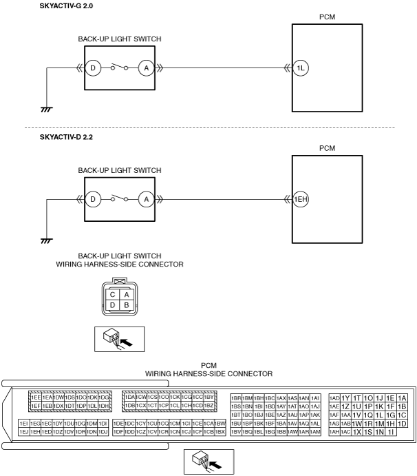
System Wiring Diagram
ac5wzw00007885
|
Diagnostic Procedure
|
Step |
Inspection |
Action |
|
|---|---|---|---|
|
1
|
VERIFY ALL SYSTEM DTCs
• Switch the ignition off.
• Switch the ignition ON (engine off or on) and wait for 10 s or more.
• Perform a CMDTC self-test using the M-MDS.
• Are any DTCs displayed?
|
Yes
|
Repair or replace the malfunctioning part according to the applicable DTC troubleshooting.
|
|
No
|
Go to the next step.
|
||
|
2
|
VERIFY IF THE ELECTRIC PARKING BRAKE WARNING LIGHT IS TURNED ON
• Verify if the electric parking brake warning light is turned on.
• Is the electric parking brake warning light turned on?
|
Yes
|
Perform an inspection referring to “ELECTRIC PARKING BRAKE WARNING LIGHT TURNS ON”.
|
|
No
|
ATX:
• Replace the electric parking brake control module.
MTX:
• Go to the next step.
|
||
|
3
|
VERIFY IF BACK-UP LIGHTS ARE ILLUMINATED
• Shift the shift lever to the reverse position.
• Are the back-up lights illuminated?
|
Yes
|
Replace the electric parking brake control module.
|
|
No
|
Go to the next step.
|
||
|
4
|
INSPECT BACK-UP LIGHT SWITCH CONNECTOR CONDITION
• Switch the ignition off.
• Disconnect the negative battery cable.
• Disconnect the back-up light switch connector.
• Inspect the connector engagement and connection condition and inspect the terminals for damage, deformation, corrosion, or disconnection.
• Is the connector normal?
|
Yes
|
Go to the next step.
|
|
No
|
Repair or replace the connector.
|
||
|
5
|
INSPECT BACK-UP LIGHT SWITCH
• Inspect the back-up light switch.
• Is the back-up light switch normal?
|
Yes
|
Go to the next step.
|
|
No
|
Replace the back-up light switch.
|
||
|
6
|
INSPECT BACK-UP LIGHT SWITCH GROUND CIRCUIT FOR OPEN CIRCUIT
• Verify that the back-up light switch connector is disconnected.
• Inspect the wiring harness for continuity between back-up light switch terminal D (wiring harness-side) and body ground.
• Is there continuity?
|
Yes
|
Go to the next step.
|
|
No
|
Refer to the wiring diagram and verify whether or not there is a common connector between back-up light switch terminal D and body ground.
If there is a common connector:
• Determine the malfunctioning part by inspecting the common connector and the terminal for corrosion, damage, or pin disconnection, and the common wiring harness for an open circuit.
• Repair or replace the malfunctioning part.
If there is no common connector:
• Repair or replace the wiring harness which has an open circuit.
|
||
|
7
|
INSPECT PCM CONNECTOR CONDITION
• Disconnect the PCM connector.
• Inspect the connector engagement and connection condition and inspect the terminals for damage, deformation, corrosion, or disconnection.
• Is the connector normal?
|
Yes
|
Go to the next step.
|
|
No
|
Repair or replace the connector.
|
||
|
8
|
INSPECT BACK-UP LIGHT SWITCH CIRCUIT FOR SHORT TO GROUND
• Verify that the back-up light switch and PCM connectors are disconnected.
• Inspect for continuity between back-up light switch terminal A (wiring harness-side) and body ground.
• Is there continuity?
|
Yes
|
Refer to the wiring diagram and verify whether or not there is a common connector between the following terminals:
• SKYACTIV-G 2.0
• SKYACTIV-D 2.2
If there is a common connector:
• Determine the malfunctioning part by inspecting the common connector and the terminal for corrosion, damage, or pin disconnection, and the common wiring harness for a short to ground.
• Repair or replace the malfunctioning part.
If there is no common connector:
• Repair or replace the wiring harness which has a short to ground.
|
|
No
|
Go to the next step.
|
||
|
9
|
INSPECT BACK-UP LIGHT SWITCH CIRCUIT FOR SHORT TO POWER SUPPLY
• Verify that the back-up light switch and PCM connectors are disconnected.
• Connect the negative battery cable.
• Switch the ignition ON (engine off or on).
• Measure the voltage at the back-up light switch terminal A (wiring harness-side).
• Is the voltage 0 V?
|
Yes
|
Go to the next step.
|
|
No
|
Refer to the wiring diagram and verify whether or not there is a common connector between the following terminals:
• SKYACTIV-G 2.0
• SKYACTIV-D 2.2
If there is a common connector:
• Determine the malfunctioning part by inspecting the common connector and the terminal for corrosion, damage, or pin disconnection, and the common wiring harness for a short to power supply.
• Repair or replace the malfunctioning part.
If there is no common connector:
• Repair or replace the wiring harness which has a short to power supply.
|
||
|
10
|
INSPECT BACK-UP LIGHT CIRCUIT FOR OPEN CIRCUIT
• Switch the ignition off.
• Disconnect the negative battery cable.
• Verify that the back-up light switch and PCM connectors are disconnected.
• Inspect for continuity between the following terminals (wiring harness-side):
• Is there continuity?
|
Yes
|
Replace the PCM.
|
|
No
|
Refer to the wiring diagram and verify whether or not there is a common connector between the following terminals:
• SKYACTIV-G 2.0
• SKYACTIV-D 2.2
If there is a common connector:
• Determine the malfunctioning part by inspecting the common connector and the terminal for corrosion, damage, or pin disconnection, and the common wiring harness for an open circuit.
• Repair or replace the malfunctioning part.
If there is no common connector:
• Repair or replace the wiring harness which has an open circuit.
|
||