 |
am6zzw00009023
OIL COOLER REMOVAL/INSTALLATION [FW6A-EL, FW6AX-EL]
id0517h2117500
1. Disconnect the negative battery cable. (See NEGATIVE BATTERY CABLE DISCONNECTION/CONNECTION [SKYACTIV-G 2.0, SKYACTIV-G 2.5 (WITHOUT i-stop)].) (See NEGATIVE BATTERY CABLE DISCONNECTION/CONNECTION [SKYACTIV-G 2.0, SKYACTIV-G 2.5].)
2. Remove the front under cover NO.2. (See FRONT UNDER COVER No.1 REMOVAL/INSTALLATION.)
3. Drain the ATF. (See AUTOMATIC TRANSAXLE FLUID (ATF) REPLACEMENT [FW6A-EL, FW6AX-EL].)
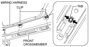
4. Disconnect the wiring harness from the front crossmember. (Vehicle with i-ELOOP)
am6zzw00009023
|
5. Drain the engine coolant. (See ENGINE COOLANT REPLACEMENT [SKYACTIV-G 2.0, SKYACTIV-G 2.5].)
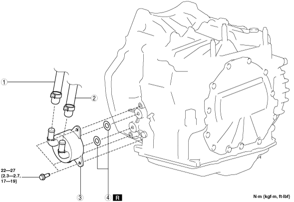
6. Remove in the order indicated in the table.
am3uuw00009170
|
|
1
|
Water hose (connected to the water pipe)
|
|
2
|
Water hose (connected to the outlet)
|
|
3
|
Water-cooled oil cooler
|
|
4
|
O-rings
|
7. Install in the reverse order of removal.
8. Add the engine coolant. (See ENGINE COOLANT REPLACEMENT [SKYACTIV-G 2.0, SKYACTIV-G 2.5].)
9. Add the ATF. (See AUTOMATIC TRANSAXLE FLUID (ATF) REPLACEMENT [FW6A-EL, FW6AX-EL].)
10. Perform the “Mechanical System Test”. (See MECHANICAL SYSTEM TEST [FW6A-EL, FW6AX-EL].)
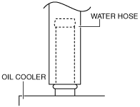
Water Hose Installation Note
1. Install the water hose to the oil cooler as shown in the figure with the hose clamp expanded.
am3uuw00008323
|
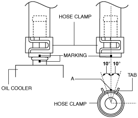
2. Install the hose clamp so that center A of the hose clamp tab is within the range shown in the figure.
ac5wzw00004590
|
3. Verify that the hose clamp does not interfere with any other components.