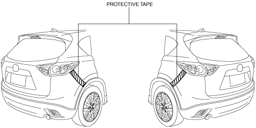
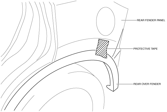
Caution
• Affix the protective tape to the position (body side) shown in the figure.
ac5uuw00001960
|
REAR BUMPER REMOVAL/INSTALLATION
id091000800700
ac5uuw00001960
|
1. Disconnect the negative battery cable. (See NEGATIVE BATTERY CABLE DISCONNECTION/CONNECTION [SKYACTIV-G 2.0, SKYACTIV-G 2.5].) (See NEGATIVE BATTERY CABLE DISCONNECTION/CONNECTION [SKYACTIV-G 2.0, SKYACTIV-G 2.5 (WITHOUT i-stop)].) (See NEGATIVE BATTERY CABLE DISCONNECTION/CONNECTION [SKYACTIV-D 2.2].)
2. Remove the rear combination light. (See REAR COMBINATION LIGHT REMOVAL/INSTALLATION.)
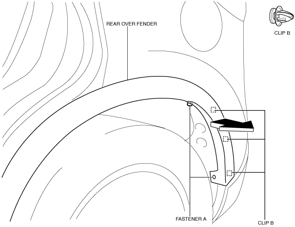
3. Remove fasteners A.
ac5wzw00003411
|
4. Pull the rear over fender in the direction of the arrow shown in the figure above, then peel it back while removing clips B.
5. Remove the rear splash shield. (See SPLASH SHIELD REMOVAL/INSTALLATION.)
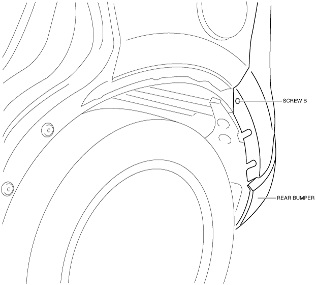
6. Remove screw B.
ac5wzw00001155
|
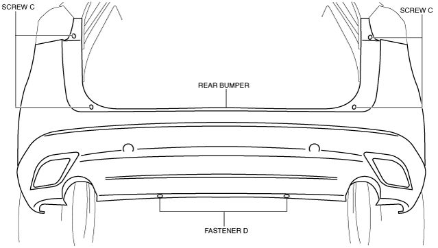
7. Remove screws C.
ac5wzw00001156
|
8. Remove fasteners D.
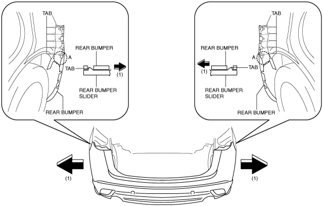
9. Pull the end of the rear bumper (A) in the direction of the arrow (1) shown in the figure, while removing tabs.
ac5uuw00001815
|
10. Remove the rear bumper from rear bumper slider.
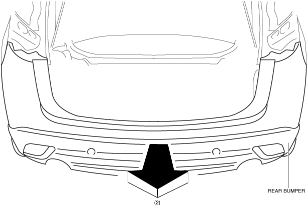
11. Remove the rear bumper in the direction of the arrow (2) shown in the figure.
ac5uuw00001816
|
12. Disconnect the rear fog light connector. (with rear fog light)
13. Disconnect the rear ultrasonic sensor connector. (with parking sensor system)
ac5uuw00001961
|
14. Install in the reverse order of removal.
15. If the rear bumper is replaced, perform the blind spot monitoring (BSM) radar test. (with blind spot monitoring system) (See BLIND SPOT MONITORING (BSM) RADAR TEST [Australian specs.].)(See BLIND SPOT MONITORING (BSM) RADAR AIMING [Except Australian specs.].)