ac5wzn00003381
|
SEAT WARMER SYSTEM
id091300101200
Purpose
Function
ac5wzn00003381
|
|
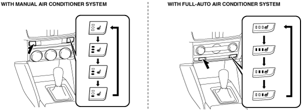
Switch display |
Temperature level |
Average temperature around seat warmer unit |
||
|---|---|---|---|---|
|
With manual air conditioner system |
With full-auto air conditioner system |
Seat cushion side |
Seat back side |
|
 |
 |
0
|
—
|
|
 |
 |
1
|
Approx. 37°C {99°F}
|
|
 |
 |
2
|
Approx. 40°C {104°F}
|
Approx. 42°C {108°F}
|
 |
 |
3
|
Approx. 42°C {108°F}
|
Approx. 47°C {117°F}
|
|
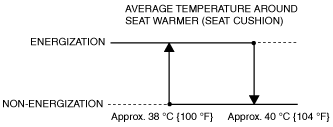
Temperature level
|
Average temperature around seat warmer unit (seat cushion side)
|
|||
|
Cloth type
|
Leather type
|
|||
|
Increase start temperature
|
Decrease start temperature
|
Increase start temperature
|
Decrease start temperature
|
|
|
0
|
—
|
|||
|
1
|
Approx. 22°C {72°F}
|
Approx. 24°C {75°F}
|
Approx. 22°C {72°F}
|
Approx. 24°C {75°F}
|
|
2
|
Approx. 32°C {90°F}
|
Approx. 34°C {93°F}
|
Approx. 32°C {90°F}
|
Approx. 34°C {93°F}
|
|
3
|
Approx. 38°C {100°F}
|
Approx. 40°C {104°F}
|
Approx. 39°C {102°F}
|
Approx. 41°C {106°F}
|
Ex.) Cloth-type temperature level is 3:
ac5wzn00003386
|
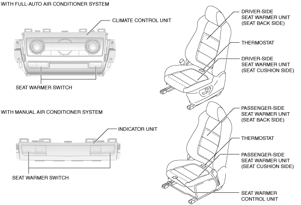
Structural view
ac5wzn00003387
|
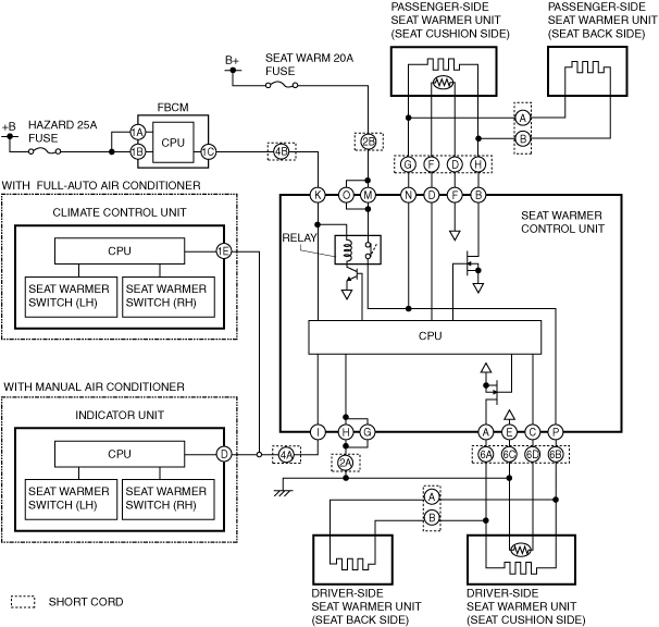
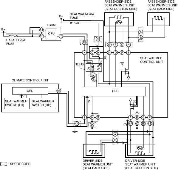
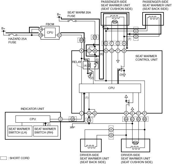
System wiring diagram
ac5uuw00004880
|
Operation
Ex.) Seat warmer temperature level on cloth-type driver's side is set at 3 (with full-auto air conditioner system):
1. When the climate control unit detects the seat warmer switch (driver’s side) operation, it sends (1) a switch operation signal (temperature level “3”) to the CPU of the seat warmer control unit.
2. When the CPU of the seat warmer control unit receives the switch operation signal (temperature level “3”) from the climate control unit, it sends current to the transistor to turn it on (2).
3. Current flows (3) to the FET by turning the transistor on.
4. The current flows (4) to the relay coil to turn the relay switch on (5).
5. When the relay switch is turned on, the ground circuit is established and the current flows (6) to the seat warmer unit in the driver’s side seat cushion and seat back.
6. The heating wire warms up (7) by the current sent to the seat warmer unit in the driver’s side seat cushion and seat back.
ac5uun00002146
|
Ex.) Seat warmer temperature level on cloth-type passenger-side is set at 3 (with manual air conditioner system):
1. When the indicator unit detects the seat warmer switch (passenger’s side) operation, it sends (1) a switch operation signal (temperature level “3”) to the CPU of the seat warmer control unit.
2. When the CPU of the seat warmer control unit receives the switch operation signal (temperature level “3”) from the indicator unit, it sends current to the transistor to turn it on (2).
3. Current flows (3) to the FET by turning the transistor on.
4. The current flows (4) to the relay coil to turn the relay switch on (5).
5. When the relay switch is turned on, the ground circuit is established and the current flows (6) to the seat warmer unit in the passenger’s side seat cushion and seat back.
6. The heating wire warms up (7) by the current sent to the seat warmer unit in the passenger’s side seat cushion and seat back.
ac5wzn00003575
|
Fail-safe