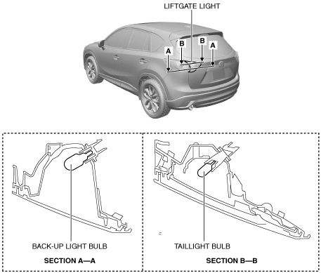
LIFTGATE LIGHT
id091800011900
Purpose
• The liftgate lights are used to signal the following conditions to vehicles/people at the rear.
-
― Back-up lights: Signals that the vehicle is backing up.
― Taillights: Signals the presence of the vehicle during nighttime.
Function
• The back-up lights are illuminated in conjunction with the shift operation.
• The taillights are illuminated in conjunction with the light switch operation (TNS).
Construction
• A bulb type or LED type is available for the liftgate light.
Bulb type
-
• The liftgate light groups the following parts.
-
― Back-up light bulb
― Taillight bulb
-
Note
-
• Fogging or condensation may occur inside the liftgate lights, however, it is a natural phenomenon occurring as a result of a temperature difference between the interior and exterior of the liftgate lights and has no effect on the light performance. Fogging or condensation will dissipate when the temperature inside the liftgate lights rises after the back-up light bulb is illuminated and a period of time has elapsed.
LED type
-
• The liftgate light groups the back-up light bulb.
• The liftgate light is integrated with the taillight (LED).
-
Note
-
• Fogging or condensation may occur inside the liftgate lights, however, it is a natural phenomenon occurring as a result of a temperature difference between the interior and exterior of the liftgate lights and has no effect on the light performance. Fogging or condensation will dissipate when the temperature inside the liftgate lights rises after the back-up light is illuminated and a period of time has elapsed.
Operation
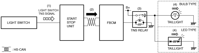
Taillights
1. When the light switch is operated to the TNS position, a light switch TNS signal is input to the start stop unit.
2. The start stop unit sends the light switch TNS signal to the front body control module (FBCM).
3. When the front body control module (FBCM) receives the light switch TNS signal, it turns the TNS relay on.
4. When the TNS relay turns on, the taillights are illuminated.
Buck-up lights
-
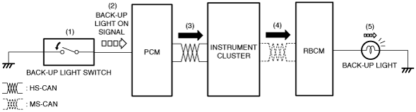
MTX
-
1. When the shift lever is operated to the reverse position, the back-up light switch is turned on.
2. When the back-up light switch is turned on, a back-up light on signal is input to the PCM.
3. The PCM sends the back-up light switch on signal to the instrument cluster.
4. The instrument cluster sends the back-up light switch on signal to the rear body control module (RBCM).
5. When the rear body control module (RBCM) receives the back-up light switch on signal, the back-up lights are illuminated.
-
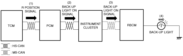
ATX
-
1. When the selector lever is operated to the R position, the TCM sends an R position signal to the PCM.
2. When the PCM receives the R position signal, it sends a back-up light on signal to the instrument cluster.
3. The instrument cluster sends the back-up light switch on signal to the rear body control module (RBCM).
4. When the rear body control module (RBCM) receives the back-up light on signal, the back-up lights are illuminated.
Fail-safe
• Not applicable