|
ac5wzw00005108
REAR MOUNT CAMERA INSPECTION
id092000815000
Fixed assist lines display type
1. Disconnect the negative battery cable. (See NEGATIVE BATTERY CABLE DISCONNECTION/CONNECTION [SKYACTIV-G 2.0, SKYACTIV-G 2.5].) (See NEGATIVE BATTERY CABLE DISCONNECTION/CONNECTION [SKYACTIV-G 2.0, SKYACTIV-G 2.5 (WITHOUT i-stop)].) (See NEGATIVE BATTERY CABLE DISCONNECTION/CONNECTION [SKYACTIV-D 2.2].)
2. Remove the following parts:
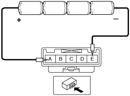
3. Prepare four dry cell batteries (1.5 V)
4. Connect the four dry cell batteries in a series.
ac5wzw00005108
|
5. Connect the positive pole of the dry cell battery to rear mount camera terminal A, and the negative pole to terminal E.
ac5wzw00004640
|
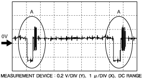
6. With the cell batteries being connected, measure the waveform between rear mount camera terminal C and terminal D.
7. Verify that waveform A shown in the figure is displayed two times or more.
ac9wzw00002991
|
Predicted vehicle path assist lines display type
1. Disconnect the negative battery cable. (See NEGATIVE BATTERY CABLE DISCONNECTION/CONNECTION [SKYACTIV-G 2.0, SKYACTIV-G 2.5].) (See NEGATIVE BATTERY CABLE DISCONNECTION/CONNECTION [SKYACTIV-G 2.0, SKYACTIV-G 2.5 (WITHOUT i-stop)].) (See NEGATIVE BATTERY CABLE DISCONNECTION/CONNECTION [SKYACTIV-D 2.2].)
2. Remove the following parts:
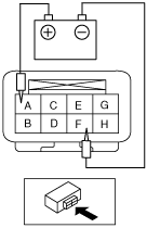
3. Apply battery voltage to rear mount camera terminal A, and connect terminal F to ground.
ac5wzw00008306
|
4. With the battery voltage being connected, measure the waveform between rear mount camera terminal C and terminal E.
5. Verify that waveform A shown in the figure is displayed two times or more.
ac9wzw00002991
|