 |
ac5uun00002122
ON-BOARD DIAGNOSTIC SYSTEM [LASER SENSOR]
id1502b2705000
Outline
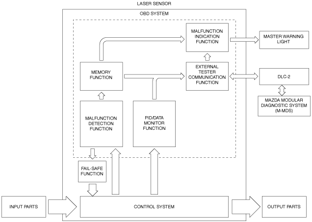
Block diagram
ac5uun00002122
|
Function
Malfunction detection function
Malfunction display function
Memory function
DTC table
|
DTC |
Master warning light |
Description |
Fail-safe |
Drive cycle |
Self test type*1 |
Memory function |
|---|---|---|---|---|---|---|
|
U0001:00
|
Illuminates
|
CAN line
|
×
|
—
|
C
|
×
|
|
U0100:00
|
||||||
|
U0121:00
|
||||||
|
U0131:00
|
||||||
|
U0155:00
|
||||||
|
U0401:00
|
Illuminates
|
Signal error from PCM
|
×
|
—
|
C
|
×
|
|
U0401:82
|
||||||
|
U0415:00
|
Illuminates
|
Signal error from DSC HU/CM
|
×
|
—
|
C
|
×
|
|
U0415:68
|
||||||
|
U0415:82
|
||||||
|
U0420:00
|
Illuminates
|
Signal error from EPS control module
|
×
|
—
|
C
|
×
|
|
U0420:82
|
||||||
|
U0423:00
|
Illuminates
|
Signal error from instrument cluster
|
×
|
—
|
C
|
×
|
|
U0423:82
|
||||||
|
U1A14:49
|
Illuminates
|
Laser sensor
|
×
|
—
|
C
|
×
|
|
U2300:54
|
Illuminates
|
Laser sensor configuration
|
×
|
—
|
C
|
×
|
|
U2300:55
|
||||||
|
U2300:56
|
||||||
|
U2300:64
|
||||||
|
U3000:00
|
Illuminates
|
Laser sensor (internal malfunction)
|
×
|
—
|
C
|
×
|
|
U3000:64
|
||||||
|
U3000:66
|
Illuminates
|
Smart City Brake Support (SCBS) system
|
×
|
—
|
C
|
×
|
|
U3003:16
|
Not illuminate
|
Battery power supply
|
×
|
—
|
C
|
×
|
|
U3003:17
|
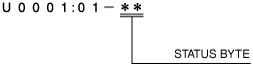
Status byte for DTC
am2zzn00002656
|
Fail-safe function
Fail-safe function table
|
DTC |
Smart City Brake Support (SCBS) control |
|---|---|
|
U0001:00
|
Control disabled
|
|
U0100:00
|
Control disabled
|
|
U0121:00
|
Control disabled
|
|
U0131:00
|
Control disabled
|
|
U0155:00
|
Control disabled
|
|
U0401:00
|
Control disabled
|
|
U0401:82
|
Control disabled
|
|
U0415:00
|
Control disabled
|
|
U0415:68
|
Control disabled
|
|
U0415:82
|
Control disabled
|
|
U0420:00
|
Control disabled
|
|
U0420:82
|
Control disabled
|
|
U0423:00
|
Control disabled
|
|
U0423:82
|
Control disabled
|
|
U1A14:49
|
Control disabled
|
|
U2300:54
|
Control disabled
|
|
U2300:55
|
Control disabled
|
|
U2300:56
|
Control disabled
|
|
U2300:64
|
Control disabled
|
|
U3000:00
|
Control disabled
|
|
U3000:64
|
Control disabled
|
|
U3000:66
|
Control disabled
|
|
U3003:16
|
Control disabled
|
|
U3003:17
|
Control disabled
|
Snapshot data
|
Snapshot data item |
Unit |
Definition |
Data read/use method |
Corresponding data monitor items |
|---|---|---|---|---|
|
AAT
|
°C, °F
|
Ambient air temperature
|
—
|
—
|
|
APP_STATUS
|
Accelerator Pedal Off/
Under 20%/
Over 20%/
FAIL
|
Accelerator pedal position
|
—
|
—
|
|
CFG_STATUS
|
Config Complete/
Not Configured/
Config Error
|
Configuration status
|
—
|
—
|
|
ECT_STATUS
|
Under 0 degrees C/
0 - Under 80 degrees C/
Over 80 degrees C/
FAIL
|
Engine coolant temperature status
|
—
|
—
|
|
IC_VPWR
|
V
|
Instrument cluster power supply
|
• The laser sensor constantly receives the power supply voltage value of the instrument cluster sent via CAN signal from the instrument cluster.
• If a DTC is detected, the laser sensor records the power supply voltage of the instrument cluster when the DTC was detected, and it is displayed in the M-MDS.
|
VPWR*1
|
|
IG-ON_TIMER
|
hh:mm:ss*2
|
Elapsed time since ignition was switched ON
|
• The laser sensor constantly receives the elapsed time since the ignition was switched ON sent via CAN signal from the instrument cluster.
• If a DTC is detected, the laser sensor records the elapsed time since the ignition was switched ON when the DTC was detected, and it is displayed in the M-MDS.
|
—
|
|
PWR_MODE_KEY
|
Key Out/Key Recently Out/Key Approved (Position 0)/Post Accessory (Position 0)/Accessory (Position 1)/Post Ignition (Position 1)/Ignition On (Position 2)/Running (Position 2)/Running - Starting In Progress (Position 2)/Crank (Position 3)
|
• Key Out: Ignition switched off
• Key Recently Out (Position 0): Elapsed time within 3 s since ignition was switched off
• Accessory (Position 1): Ignition is switched to ACC
• Post Ignition (Position 2): Elapsed time within 3 s since ignition was switched ON
• Ignition On (Position 2): Ignition switched ON (engine off)
• Running (Position 2): Ignition switched ON (engine on)
• Running - Starting: Cranking condition
|
• The laser sensor constantly receives the ignition switch status sent via CAN signal from the instrument cluster.
• If a DTC is detected, the laser sensor records the ignition switch status when the DTC was detected, and it is displayed in the M-MDS.
|
—
|
|
RPM_STATUS
|
Engine Stop/
Under 1500 rpm/
Over 1500 rpm/
FAIL
|
Engine RPM status
|
• The laser sensor constantly receives the ignition switch status sent via CAN signal from the instrument cluster.
• If a DTC is detected, the laser sensor records the ignition switch status when the DTC was detected, and it is displayed in the M-MDS.
|
TACHOMTR*1
|
|
SHIFT_STATUS
|
P/N
D/
R/
FAIL
|
Shift position status
|
• The laser sensor constantly receives the selector lever position sent via CAN signal from the instrument cluster.
• If a DTC is detected, the laser sensor records the selector lever position when the DTC was detected, and it is displayed in the M-MDS.
|
—
|
|
TOTAL_DIST
|
km, ft, mi
|
Accumulated total traveled distance from completion of vehicle until laser sensor detects DTC (Odometer value in instrument cluster)
|
The distance traveled when the laser sensor detected a DTC can be calculated by performing the following procedure.
1. Verify the odometer value in the instrument cluster.
2. Verify the snap shot data item TOTAL_DIST.
3. Subtract 2 from 1.
|
—
|
|
TOTAL_TIME
|
hh:mm:ss*2
|
Accumulated total elapsed time since vehicle completion until laser sensor detects a DTC
|
The elapsed time when the laser sensor detected a DTC can be calculated by performing the following procedure.
1. Verify the PID item TOTAL_TIME of the instrument cluster.
2. Verify the snap shot data item TOTAL_TIME.
3. Subtract 2 from 1.
|
TOTAL_TIME*1
|
|
VPWR
|
V
|
Power supply
|
—
|
VPWR_IG1
|
|
VSPD_STATUS
|
Stop/
0 - 10 km/h/
Over 10 km/h/
FAIL
|
Vehicle speed status
|
• The laser sensor constantly receives the vehicle speed sent via CAN signal from the instrument cluster.
• If a DTC is detected, the laser sensor records the vehicle speed when the DTC was detected, and it is displayed in the M-MDS.
|
SPEEDOMTR*1
|
PID/data monitor function
|
Monitor item (Mazda Modular Diagnostic System (M-MDS) display) |
Definition |
Unit/operation |
|---|---|---|
|
DST_BMP_TGT
|
Distance from front bumper to target that laser sensor has detected
|
m, ft
|
|
VPWR_IG1
|
Power supply
|
V
|
|
VSPD
|
Vehicle speed
|
KPH, MPH
|
External tester communication function
|
Diagnostic function name |
Signal received |
Signal sent |
|---|---|---|
|
Malfunction detection function
|
DTC verification signal
|
DTC(s)
|
|
PID/data monitor function
|
Command signal to read selected monitor item
|
Monitored data for requested monitor item
|