DTC B118D:11 [BLIND SPOT MONITORING (BSM) CONTROL MODULE (Australian specs.)]


id1502b7013100

Caution
•  Configuration cannot be implemented correctly if only the blind spot monitoring (BSM) control module (RH) is replaced. When replacing the blind spot monitoring (BSM) control module (RH), it is necessary to replace the blind spot monitoring (BSM) control module (LH) at the same time.

Description

Blind spot monitoring (BSM) indicator light (RH) circuit malfunction

Detection condition
•  Blind spot monitoring (BSM) control module (RH) performs measurement at 0.01 s intervals and a short to ground in the blind spot monitoring (BSM) indicator light (RH) circuit is detected 48 times continuously.
Fail-safe
•  Blind spot monitoring (BSM) system is stopped.
Possible cause
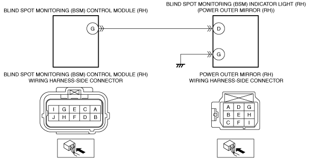
•  Power outer mirror (RH) connector or terminal malfunction
•  Blind spot monitoring (BSM) control module (RH) connector or terminal malfunction
•  Short to ground in wiring harness between blind spot monitoring (BSM) control module (RH) terminal G and power outer mirror (RH) terminal D
•  Blind spot monitoring (BSM) indicator light (RH) malfunction
•  Blind spot monitoring (BSM) control module (RH) malfunction

Diagnostic Procedure

Step

Inspection

Action

1
INSPECT POWER OUTER MIRROR (RH) CONNECTOR CONDITION
•  Switch the ignition off.
•  Disconnect the power outer mirror (RH) connector.
•  Inspect the connector engagement and connection condition and inspect the terminals for damage, deformation, corrosion, or disconnection.
•  Is the connector normal?
Yes
Go to the next step.
No
Repair or replace the connector, then go to Step 5.
2
INSPECT BLIND SPOT MONITORING (BSM) CONTROL MODULE (RH) CONNECTOR CONDITION
•  Disconnect the blind spot monitoring (BSM) control module (RH) connector.
•  Inspect the connector engagement and connection condition and inspect the terminals for damage, deformation, corrosion, or disconnection.
•  Is the connector normal?
Yes
Go to the next step.
No
Repair or replace the connector, then go to Step 5.
3
INSPECT FOR SHORT TO GROUND IN BLIND SPOT MONITORING (BSM) INDICATOR LIGHT (RH) CIRCUIT
•  Verify that the blind spot monitoring (BSM) control module (RH) and power outer mirror (RH) connectors are disconnected.
•  Inspect for continuity between power outer mirror (RH) terminal D (wiring harness-side) and body ground.
•  Is there continuity?
Yes
Refer to the wiring diagram and verify whether or not there is a common connector between blind spot monitoring (BSM) control module (RH) terminal G and power outer mirror (RH) terminal D.
If there is a common connector:
•  Determine the malfunctioning part by inspecting the common connector and the terminal for corrosion, damage, or pin disconnection, and the common wiring harness for a short to ground.
•  Repair or replace the malfunctioning part.
If there is no common connector:
•  Repair or replace the wiring harness which has a short to ground.
Go to Step 5.
No
Go to the next step.
4
INSPECT BLIND SPOT MONITORING (BSM) INDICATOR LIGHT (RH)
•  Inspect the blind spot monitoring (BSM) indicator light (RH).
•  Is the blind spot monitoring (BSM) indicator light (RH) normal?
Yes
Go to the next step.
No
Replace the power outer mirror (RH) or outer mirror glass (RH), then go to the next step.
5
VERIFY THAT REPAIRS HAVE BEEN COMPLETED
•  Always reconnect all disconnected connectors.
•  Clear the blind spot monitoring (BSM) control module (RH) DTCs using the M-MDS.
•  Retrieve the blind spot monitoring (BSM) control module (RH) DTCs using the M-MDS.
•  Is the same DTC displayed?
Yes
Repeat the inspection from Step 1.
•  If the malfunction recurs, replace the blind spot monitoring (BSM) control module.
Go to the next step.
No
Go to the next step.
6
VERIFY IF OTHER DTCs DISPLAYED
•  Are any other DTCs displayed?
Yes
Repair or replace the malfunctioning part according to the applicable DTC troubleshooting.
No
DTC troubleshooting completed.