|
1
|
VERIFY RELATED REPAIR INFORMATION AVAILABILITY
• Verify related Service Bulletins and/or on-line repair information availability.
• Is any related repair information available?
|
Yes
|
Perform repair or diagnosis according to the available repair information.
• If the vehicle is not repaired, go to the next step.
|
|
No
|
Go to the next step.
|
|
2
|
VERIFY DTC FOR MODULE COMMUNICATION
• Switch the ignition off, then ON (engine off).
• Perform the DTC Reading Procedure.
• Is the DTC U0155:00 also present?
|
Yes
|
Go to the applicable DTC inspection.
(See DTC U0073:00, U0101:00, U0104:00, U010E:00, U0121:00, U0131:00, U0140:00, U0151:00, U0155:00, U0214:00, U023A:00, U029D:00 [PCM (SKYACTIV-D 2.2)].) |
|
No
|
Go to the next step.
|
|
3
|
CONFIRM FRONT BODY CONTROL MODULE (FBCM) DTC
• Perform the front body control module (FBCM) DTC inspection using the M-MDS.
• Are any DTCs present?
|
Yes
|
Go to the applicable DTC inspection.
|
|
No
|
Go to the next step.
|
|
4
|
CONFIRM FRONT BODY CONTROL MODULE (FBCM) DTC
• Perform the front body control module (FBCM) DTC inspection using the M-MDS.
• Are any DTCs present?
|
Yes
|
Go to the applicable DTC inspection.
|
|
No
|
Go to the next step.
|
|
5
|
CONFIRM ACTIVE DRIVING DISPLAY DTC
• Perform the active driving display DTC inspection using the M-MDS.
• Are any DTCs present?
|
Yes
|
Go to the applicable DTC inspection.
|
|
No
|
Go to the next step.
|
|
6
|
CONFIRM INSTRUMENT CLUSTER DTC
• Perform the instrument cluster DTC inspection using the M-MDS.
• Are any DTCs present?
|
Yes
|
DTC U0100:00 is displayed:
• CAN communication line can be considered the cause.
-
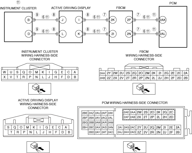
― Refer to the wiring diagram and verify whether or not there is a common connector between the following terminals:
-
• Instrument cluster terminal B—active driving display terminal J
• Instrument cluster terminal D—active driving display terminal L
• Active driving display terminal I—Front body control module (FBCM) terminal 2K
• Active driving display terminal K—Front body control module (FBCM) terminal 2I
• Front body control module (FBCM) terminal 2P—PCM terminal 2AK
• Front body control module (FBCM) terminal 2N—PCM terminal 2AL
If there is a common connector:
-
• Determine the malfunctioning part by inspecting the common connector and the terminal for corrosion, damage, or pin disconnection, and the common wiring harness for a malfunction.
• Repair or replace the malfunctioning part.
If there is no common connector:
-
• Repair or replace the wiring harness.
• Go to Step 12.
DTC other than U0100:00 is displayed:
• Go to the applicable DTC inspection.
|
|
No
|
Go to the next step.
|
|
7
|
INSPECT FRONT BODY CONTROL MODULE (FBCM) CONNECTOR CONDITION
• Switch the ignition off.
• Disconnect the front body control module (FBCM) connector.
• Inspect for poor connection (such as damaged/pulled-out pins, corrosion).
• Is there any malfunction?
|
Yes
|
Repair or replace the connector and/or terminals, then go to Step 12.
|
|
No
|
Go to the next step.
|
|
8
|
INSPECT ACTIVE DRIVING DISPLAY CONNECTOR CONDITION
• Switch the ignition off.
• Disconnect the active driving display connector.
• Inspect for poor connection (such as damaged/pulled-out pins, corrosion).
• Is there any malfunction?
|
Yes
|
Repair or replace the connector and/or terminals, then go to Step 12.
|
|
No
|
Go to the next step.
|
|
9
|
INSPECT INSTRUMENT CLUSTER CONNECTOR CONDITION
• Disconnect the instrument cluster connector.
• Inspect for poor connection (such as damaged/pulled-out pins, corrosion).
• Is there any malfunction?
|
Yes
|
Repair or replace the connector and/or terminals, then go to Step 12.
|
|
No
|
Go to the next step.
|
|
10
|
INSPECT INSTALLATION OF INSTRUMENT CLUSTER
• Inspect installation of instrument cluster.
• Is the instrument cluster installed securely?
|
Yes
|
Go to the next step.
|
|
No
|
Retighten the instrument cluster, then go to Step 12.
|
|
11
|
INSPECT PCM CONNECTOR CONDITION
• Disconnect the PCM connector.
• Inspect for poor connection (such as damaged/pulled-out pins, corrosion).
• Is there any malfunction?
|
Yes
|
Repair or replace the connector and/or terminals, then go to the next step.
|
|
No
|
Repair or replace the following wiring harnesses.
• Instrument cluster terminal B—active driving display terminal J
• Instrument cluster terminal D—active driving display terminal L
• Active driving display terminal I—Front body control module (FBCM) terminal 2K
• Active driving display terminal K—Front body control module (FBCM) terminal 2I
• Front body control module (FBCM) terminal 2P—PCM terminal 2AK
• Front body control module (FBCM) terminal 2N—PCM terminal 2AL
-
― If the malfunction recurs, replace the instrument cluster.
Go to the next step.
|
|
12
|
VERIFY DTC TROUBLESHOOTING COMPLETED
• Always reconnect all disconnected connectors.
• Clear the DTC from the PCM memory using the M-MDS.
• Switch the ignition ON (engine off) and wait for 15 s or more.
• Switch the ignition off.
• Wait until the main relay is off (approx. 1 min).
• Perform the DTC Reading Procedure.
• Is the same DTC present?
|
Yes
|
Repeat the inspection from Step 1.
• If the malfunction recurs, replace the PCM.
Go to the next step.
|
|
No
|
Go to the next step.
|
|
13
|
VERIFY AFTER REPAIR PROCEDURE
• Perform the “AFTER REPAIR PROCEDURE”.
• Are any DTCs present?
|
Yes
|
Go to the applicable DTC inspection.
|
|
No
|
DTC troubleshooting completed.
|