 |
ac5wzw00015009
DTC P250A:00 [PCM (WITH CYLINDER DEACTIVATION (SKYACTIV-G 2.0, SKYACTIV-G 2.5))]
id0102sd787200
Details On DTCs
|
DESCRIPTION |
Engine oil level signal: engine oil level sensor malfunction |
|
|---|---|---|
|
DETECTION CONDITION
|
Determination conditions
|
• PCM receives abnormal signal from the engine oil level sensor.
|
|
Preconditions
|
• Battery voltage: 10—16 V
• The following DTC is not detected:
• Low-G (XY) sensor (built-into SAS control module) signal is normal
|
|
|
Drive cycle
|
• 1
|
|
|
Self test type
|
• CMDTC self test
|
|
|
Sensor used
|
• Engine oil level sensor
• Engine oil level sensor internal temperature sensor
• Low-G (XY) sensor (built-into SAS control module)
|
|
|
FAIL-SAFE FUNCTION
|
• Not applicable
|
|
|
VEHICLE STATUS WHEN DTCs ARE OUTPUT
|
• Illuminates master warning light. (without multi-information display)
• The master warning indication is displayed on the multi-information display. (with multi-information display)
|
|
|
POSSIBLE CAUSE
|
• Excessive engine oil level (oil level exceeds measurable upper limit range of engine oil level sensor)
• Engine oil level sensor malfunction
• Erratic signal to PCM
• PCM malfunction
|
|
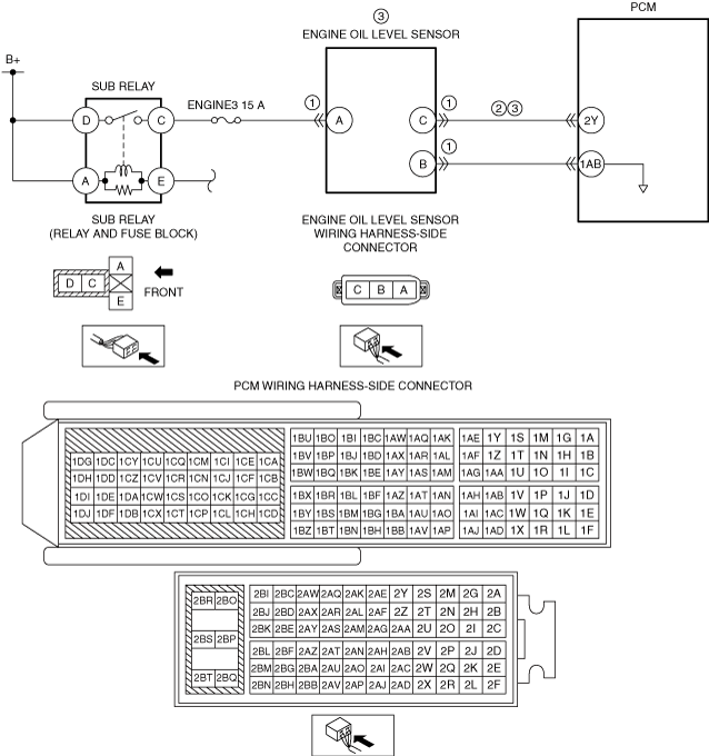
System Wiring Diagram
ac5wzw00015009
|
Function Explanation (DTC Detection Outline)
Repeatability Verification Procedure
PID Item/Simulation Item Used In Diagnosis
PID/DATA monitor item table
|
Item |
Definition |
Unit |
Condition/Specification |
|---|---|---|---|
|
EOL
|
Engine oil level
|
mm, in
|
• Displays engine oil level
|
|
EOT2
|
Engine oil temperature from engine oil level sensor
|
°C, °F
|
• Displays the engine oil temperature
|
Function Inspection Using M-MDS
|
STEP |
INSPECTION |
RESULTS |
ACTION |
|---|---|---|---|
|
1
|
PURPOSE: RECORD VEHICLE STATUS AT TIME OF DTC DETECTION TO UTILIZE WITH REPEATABILITY VERIFICATION
• Record the snapshot data on the repair order.
|
—
|
Go to the next step.
|
|
2
|
PURPOSE: VERIFY RELATED SERVICE INFORMATION AVAILABILITY
• Verify related Service Information availability.
• Is any related Service Information available?
|
Yes
|
Perform repair or diagnosis according to the available Service Information.
• If the vehicle is not repaired, go to the next step.
|
|
No
|
Go to the next step.
|
||
|
3
|
PURPOSE: IDENTIFY TRIGGER DTC FOR FREEZE FRAME DATA
• Perform the Freeze Frame PID Data Access Procedure.
• Is the DTC P250A:00 on FREEZE FRAME DATA?
|
Yes
|
Go to the next step.
|
|
No
|
Go to the troubleshooting procedure for DTC on FREEZE FRAME DATA.
|
||
|
4
|
PURPOSE: INSPECT FOR OTHER RELATED DTCs
• Perform the DTC inspection for the PCM.
• Are any other DTCs displayed?
|
Yes
|
Repair the malfunctioning location according to the applicable DTC troubleshooting.
|
|
No
|
Go to the next step.
|
||
|
5
|
PURPOSE: DETERMINE IF CAUSE IS ERROR SIGNAL FROM ENGINE OIL LEVEL SENSOR
• Clear the DTC recorded in the memory.
• Access the following PIDs using the M-MDS:
PCM:
• Start the engine and warm up until the value of PID EOT2 is 60 °C {140 °F} or more.
• After engine warm-up, perform the DTC inspection for the PCM.
• Is the same Pending DTC present?
|
Yes
|
Go to Troubleshooting Diagnostic Procedure to perform the procedure from Step 1.
|
|
No
|
Go to the next step.
|
||
|
6
|
PURPOSE: VERIFY ACTUAL ENGINE OIL LEVEL
• Switch the ignition ON (engine off) and leave for 5 min.
• Pull out the dipstick.
• Verify if the engine oil level is 8 mm {0.3 in} or more from the upper limit position of the dipstick.
• Is it 8 mm {0.3 in} or more?
|
Yes
|
Go to Step 8.
|
|
No
|
Go to the next step.
|
||
|
7
|
PURPOSE: VERIFY IF CAUSE IS ENGINE OIL LEVEL SENSOR STICKING MALFUNCTION
• Access the following PIDs using the M-MDS:
PCM:
• Start the engine while verifying the monitor value with the ignition switched ON (engine off).
• Leave for 30 s or more.
• Does the monitor value decrease by 7 mm {0.3 in} or more compared to the value with the ignition switched ON (engine off)?
|
Yes
|
A temporary malfunction can be considered.
• Perform the [Action for Non-repeatable Malfunction].
|
|
No
|
Go to Troubleshooting Diagnostic Procedure to perform the procedure from Step 1.
|
||
|
8
|
PURPOSE: VERIFY IF CAUSE IS EXCESSIVE ENGINE OIL LEVEL
• Switch the ignition ON (engine off).
• Access the following PIDs using the M-MDS:
PCM:
• Verify the monitor value with the ignition switched ON (engine off).
• Is the monitor value 74 mm {2.9 in} or more?
|
Yes
|
Adjust the engine oil level near the middle of the upper and lower limit position on the dipstick.
Go to the next step.
|
|
No
|
Go to Troubleshooting Diagnostic Procedure to perform the procedure from Step 1.
|
||
|
9
|
PURPOSE: VERIFY IF CAUSE IS ENGINE OIL LEVEL SENSOR STICKING MALFUNCTION
• Access the following PIDs using the M-MDS:
PCM:
• Start the engine while verifying the monitor value with the ignition switched ON (engine off).
• Leave for 30 s or more.
• Does the monitor value decrease by 7 mm {0.3 in} or more compared to the value with the ignition switched ON (engine off)?
|
Yes
|
The cause is an excessive engine oil amount exceeding the measurable range of the engine oil level sensor.
• Replace the engine oil because there is the possibility that the engine oil is diluted.
Go to Troubleshooting Diagnostic Procedure to perform the repair completion verification.
|
|
No
|
Go to Troubleshooting Diagnostic Procedure to perform the procedure from Step 1.
|
Troubleshooting Diagnostic Procedure
|
STEP |
INSPECTION |
RESULTS |
ACTION |
|---|---|---|---|
|
1
|
PURPOSE: INSPECT ENGINE OIL LEVEL SENSOR CONNECTOR CONDITION
• Switch the ignition off.
• Disconnect the engine oil level sensor connector.
• Inspect for poor connection (such as damaged/pulled-out pins, corrosion).
• Is there any malfunction?
|
Yes
|
Repair or replace the connector and/or terminals, then go to Step 4.
|
|
No
|
Go to the next step.
|
||
|
2
|
PURPOSE: INSPECT ENGINE OIL LEVEL SENSOR CONTROL CIRCUIT FOR SHORT TO GROUND
• Disconnect the PCM connector.
• Verify that the engine oil level sensor and PCM connectors are disconnected.
• Inspect for continuity between engine oil level sensor terminal C (wiring harness-side) and body ground.
• Is there continuity?
|
Yes
|
Refer to the wiring diagram and verify whether or not there is a common connector between engine oil level sensor terminal C and PCM terminal 2Y.
If there is a common connector:
• Determine the malfunctioning part by inspecting the common connector and the terminal for corrosion, damage, or pin disconnection, and the common wiring harness for a short to ground.
• Repair or replace the malfunctioning part.
If there is no common connector:
• Repair or replace the wiring harness which has a short to ground.
Go to Step 4.
|
|
No
|
Go to the next step.
|
||
|
3
|
PURPOSE: INSPECT ENGINE OIL LEVEL SENSOR CIRCUIT FOR OPEN CIRCUIT
• Verify that the engine oil level sensor and PCM connectors are disconnected.
• Inspect for continuity between engine oil level sensor terminal C (wiring harness-side) and PCM terminal 2Y (wiring harness-side).
• Is there continuity?
|
Yes
|
Replace the engine oil level sensor, then go to the next step.
|
|
No
|
Refer to the wiring diagram and verify whether or not there is a common connector between engine oil level sensor terminal C and PCM terminal 2Y.
If there is a common connector:
• Determine the malfunctioning part by inspecting the common connector and the terminal for corrosion, damage, or pin disconnection, and the common wiring harness for an open circuit.
• Repair or replace the malfunctioning part.
If there is no common connector:
• Repair or replace the wiring harness which has an open circuit.
Go to the next step.
|
||
|
4
|
PURPOSE: PERFORM DTC INSPECTION AND VERIFY IF MALFUNCTIONING PART IS PCM
• Always reconnect all disconnected connectors.
• Clear the DTC from the PCM memory using the M-MDS.
• Implement the repeatability verification procedure.
• Perform the DTC Reading Procedure.
• Is the same Pending DTC present?
|
Yes
|
Repeat the inspection from Step 1.
• If the malfunction recurs, replace the PCM.
Go to the next step.
|
|
No
|
Go to the next step.
|
||
|
5
|
PURPOSE: VERIFY IF THERE IS ANY OTHER MALFUNCTION
• Is any other DTC or pending code stored?
|
Yes
|
Go to the applicable DTC inspection.
|
|
No
|
DTC troubleshooting completed.
|