 |
ac5uuw00006881
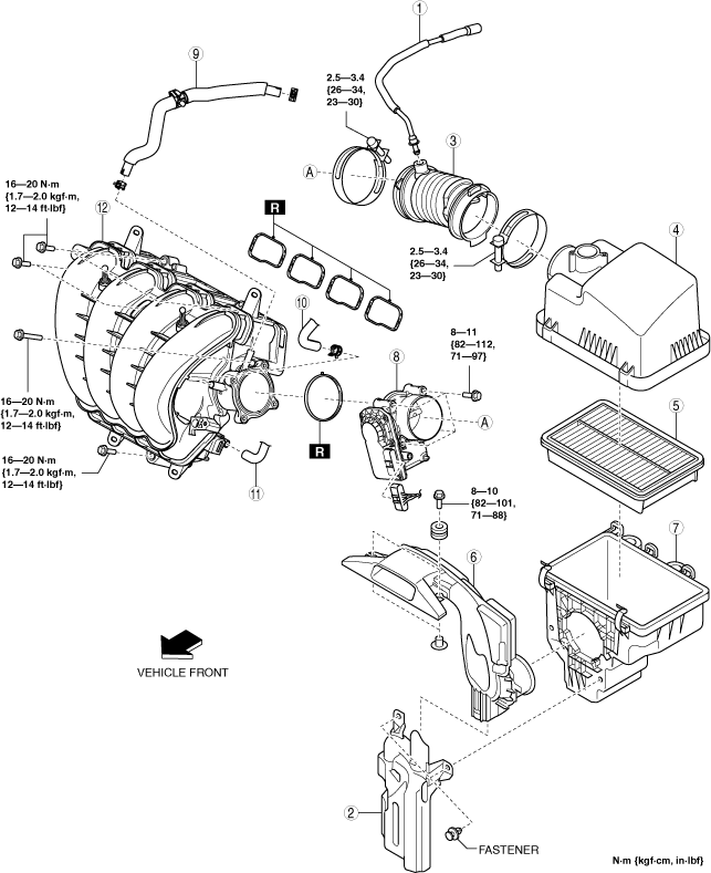
INTAKE-AIR SYSTEM REMOVAL/INSTALLATION [WITHOUT CYLINDER DEACTIVATION (SKYACTIV-G 2.0, SKYACTIV-G 2.5)]
id0113m1801900
Replacement Part
|
Intake manifold gasket
Quantity: 4
Location of use: Intake manifold
|
Throttle body gasket
Quantity: 1
Location of use: Throttle body
|
1. Disconnect the negative battery terminal. (See NEGATIVE BATTERY TERMINAL DISCONNECTION/CONNECTION.)
2. Remove in the order indicated in the table.
3. Install in the reverse order of removal.
ac5uuw00006881
|
|
1
|
Ventilation hose
|
|
2
|
Resonance chamber
|
|
3
|
Air hose
|
|
4
|
Air cleaner cover
|
|
5
|
Air cleaner element
|
|
6
|
Fresh-air duct
(See Fresh-air Duct Removal Note.)
|
|
7
|
Air cleaner case
|
|
8
|
Throttle body
(See Throttle Body Removal Note.)
|
|
9
|
Vacuum hose (between intake manifold and vacuum pump)
|
|
10
|
Evaporative hose
|
|
11
|
PCV hose
|
|
12
|
Intake manifold
|
Resonance Chamber Removal Note
1. Remove the MAF sensor/IAT sensor No.1. (See MASS AIR FLOW (MAF) SENSOR/INTAKE AIR TEMPERATURE (IAT) SENSOR NO.1 REMOVAL/INSTALLATION [WITHOUT CYLINDER DEACTIVATION (SKYACTIV-G 2.0, SKYACTIV-G 2.5)].)
2. Remove the following parts as a single unit:
3. Remove the resonance chamber.
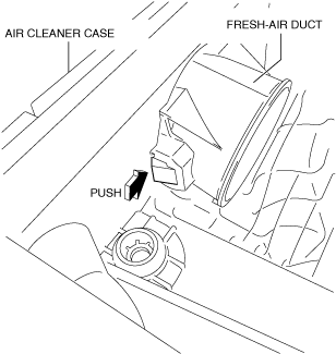
Fresh-air Duct Removal Note
1. Pull out the fresh-air duct while pressing the tab shown in the figure.
ac5uuw00000365
|
Throttle Body Removal Note
1. Remove the upper radiator hose bracket installation bolt. (See COOLING FAN MOTOR REMOVAL/INSTALLATION [WITHOUT CYLINDER DEACTIVATION (SKYACTIV-G 2.0, SKYACTIV-G 2.5)].)
2. Remove the throttle body.
Vacuum Hose (between intake manifold and vacuum pump) Removal Note
1. Remove the plug hole plate. (See PLUG HOLE PLATE REMOVAL/INSTALLATION [WITHOUT CYLINDER DEACTIVATION (SKYACTIV-G 2.0, SKYACTIV-G 2.5)].)
2. Remove the vacuum hose.
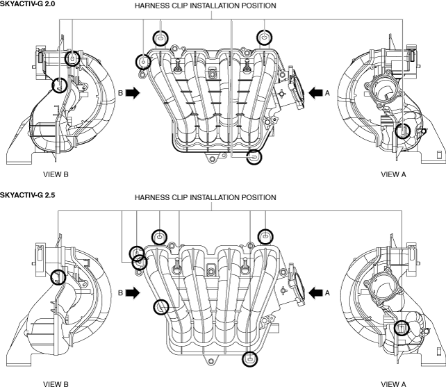
Intake Manifold Removal Note
1. Remove the MAP sensor/IAT sensor No.2. (See MANIFOLD ABSOLUTE PRESSURE (MAP) SENSOR/INTAKE AIR TEMPERATURE (IAT) SENSOR NO.2 REMOVAL/INSTALLATION [WITHOUT CYLINDER DEACTIVATION (SKYACTIV-G 2.0, SKYACTIV-G 2.5)].)
2. Disconnect the harness clip from the intake manifold as shown in the figure.
ac5wzw00012173
|
3. Remove the intake manifold.
Intake Manifold Installation Note
1. Install the intake manifold.
2. Connect the wiring harness clip to the intake manifold shown in the figure.
ac5wzw00012173
|
Evaporative Hose Installation Note
1. Install the evaporative hose as shown in the figure.
ac5uuw00002656
|
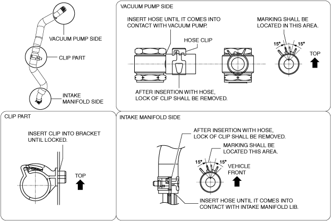
Vacuum Hose (between intake manifold and vacuum pump) Installation Note
1. Install the vacuum hose as shown in the figure.
ac5uuw00002657
|
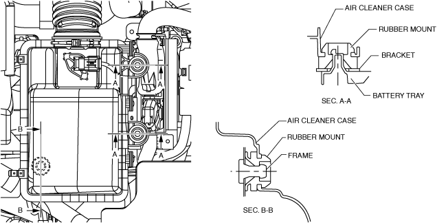
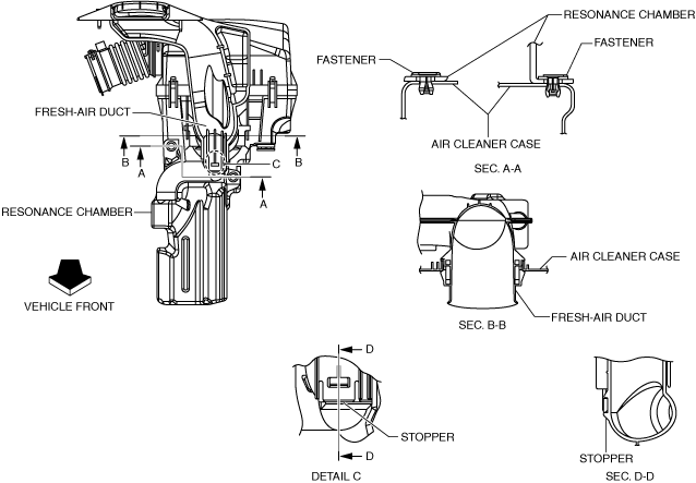
Air Cleaner Case Installation Note
1. Install the air cleaner case as shown in the figure.
ac5uuw00000367
|
Fresh-air Duct Installation Note
1. Install the fresh-air duct as shown in the figure.
ac5uuw00000368
|
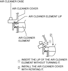
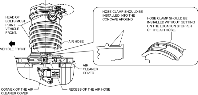
Air Cleaner Cover Installation Note
1. Install the air cleaner cover as shown in the figure.
ac5wzw00005692
|
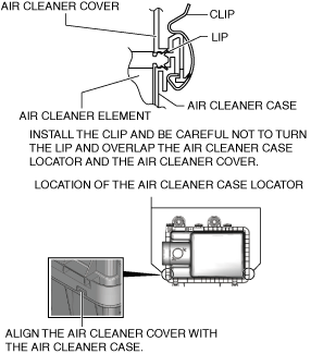
2. Secure the air cleaner cover and the air cleaner case with the clip.
ac5wzw00010720
|
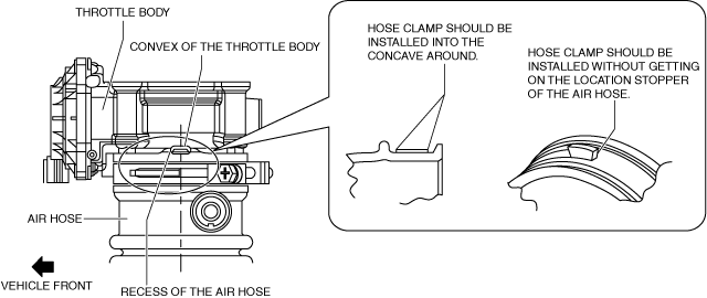
Air Hose Installation Note
1. Install the air hose as shown in the figure.
Throttle body side
ac5uuw00004520
|
Air cleaner side
ac5uuw00004521
|
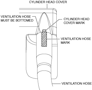
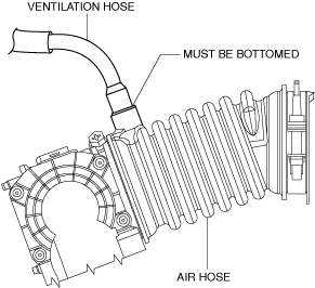
Ventilation Hose Installation Note
1. Install the ventilation hose as shown in the figure.
Cylinder head cover side
am3uuw00008002
|
Air hose side
ac5uuw00000371
|