 |
ac5uuw00009003
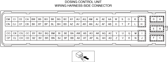
DOSING CONTROL UNIT INSPECTION [SKYACTIV-D 2.2]
id0140z7824100
Without Using The M-MDS
Terminal voltage table (Reference)
ac5uuw00009003
|
|
Terminal |
Signal |
Connected to |
Test condition |
Voltage (V) |
inspection item |
|---|---|---|---|---|---|
|
A
|
Battery voltage
|
SCR relay No.2
|
Switch the ignition ON (engine off)
|
B+
|
• SCR relay No.2
• Related wiring harness
|
|
B
|
Battery voltage
|
SCR relay No.1, No.2
|
Switch the ignition ON (engine off)
|
B+
|
• SCR relay No.1, No.2
• Related wiring harness
|
|
C
|
Battery voltage
|
SCR relay No.1, No.2
|
Switch the ignition ON (engine off)
|
B+
|
• SCR relay No.1, No.2
• Related wiring harness
|
|
D
|
Urea tank heater control
|
Urea tank heater
|
Urea tank heater operating
|
B+
|
• Urea tank heater
• Related wiring harness
|
|
Urea tank heater not operating
|
Below 1.0
|
||||
|
E
|
GND
|
GND
|
Under any condition
|
Below 1.0
|
• Related wiring harness
|
|
F
|
Urea hose heater control
|
Urea hose heater
|
Urea hose heater operating
|
B+
|
• Urea hose heater
• Related wiring harness
|
|
Urea hose heater not operating
|
Below 1.0
|
||||
|
G
|
—
|
—
|
—
|
—
|
—
|
|
H
|
Urea pump control (GND)
|
Urea pump (pumping side)
|
Depend on engine load
|
Below 1.0
|
• Urea pump
• Related wiring harness
|
|
I
|
Urea pump control (battery voltage)
|
Urea pump (pumping side)
|
Depend on engine load
|
0—B+
|
• Urea pump
• Related wiring harness
|
|
J
|
—
|
—
|
—
|
—
|
—
|
|
K
|
Urea injector control (-)
|
Urea injector
|
Depend on engine load
|
Below 1.0
|
• Urea injector
• Related wiring harness
|
|
L
|
Battery voltage
|
Urea level sensor/urea temperature sensor
|
Switch the ignition ON (engine off)
|
B+
|
• Urea level sensor/urea temperature sensor
• Related wiring harness
|
|
M
|
—
|
—
|
—
|
—
|
—
|
|
N
|
Urea injector control (+)
|
Urea injector
|
Depend on engine load
|
0—B+
|
• Urea injector
• Related wiring harness
|
|
O
|
—
|
—
|
—
|
—
|
—
|
|
P
|
—
|
—
|
—
|
—
|
—
|
|
Q
|
—
|
—
|
—
|
—
|
—
|
|
R
|
—
|
—
|
—
|
—
|
—
|
|
S
|
—
|
—
|
—
|
—
|
—
|
|
T
|
Battery voltage
|
Urea quality sensor
|
Switch the ignition ON (engine off)
|
B+
|
• Urea quality sensor
• Related wiring harness
|
|
U
|
—
|
—
|
—
|
—
|
—
|
|
V
|
—
|
—
|
—
|
—
|
—
|
|
W
|
—
|
—
|
—
|
—
|
—
|
|
X
|
—
|
—
|
—
|
—
|
—
|
|
Y
|
Urea pump control (battery voltage)
|
Urea pump (siphoning side)
|
Depend on engine load
|
0—B+
|
• Urea pump
• Related wiring harness
|
|
Z
|
—
|
—
|
—
|
—
|
—
|
|
AA
|
—
|
—
|
—
|
—
|
—
|
|
AB
|
—
|
—
|
—
|
—
|
—
|
|
AC
|
—
|
—
|
—
|
—
|
—
|
|
AD
|
—
|
—
|
—
|
—
|
—
|
|
AE
|
—
|
—
|
—
|
—
|
—
|
|
AF
|
—
|
—
|
—
|
—
|
—
|
|
AG
|
—
|
—
|
—
|
—
|
—
|
|
AH
|
—
|
—
|
—
|
—
|
—
|
|
AI
|
—
|
—
|
—
|
—
|
—
|
|
AJ
|
—
|
—
|
—
|
—
|
—
|
|
AK
|
—
|
—
|
—
|
—
|
—
|
|
AL
|
—
|
—
|
—
|
—
|
—
|
|
AM
|
—
|
—
|
—
|
—
|
—
|
|
AN
|
—
|
—
|
—
|
—
|
—
|
|
AO
|
—
|
—
|
—
|
—
|
—
|
|
AP
|
—
|
—
|
—
|
—
|
—
|
|
AQ
|
—
|
—
|
—
|
—
|
—
|
|
AR
|
Urea level/urea temperature control
|
Urea level sensor/urea temperature sensor
|
Because this terminal is for PWM (Pulse Width Modulation) signal, integrity determination by terminal voltage is not possible.
|
• Urea level sensor/urea temperature sensor
• Related wiring harness
|
|
|
AS
|
—
|
—
|
—
|
—
|
—
|
|
AT
|
—
|
—
|
—
|
—
|
—
|
|
AU
|
—
|
—
|
—
|
—
|
—
|
|
AV
|
GND
|
Urea level sensor/urea temperature sensor
|
Switch the ignition ON (engine off)
|
Below 1.0
|
• Urea level sensor/urea temperature sensor
• Related wiring harness
|
|
AW
|
—
|
—
|
—
|
—
|
—
|
|
AX
|
—
|
—
|
—
|
—
|
—
|
|
AY
|
—
|
—
|
—
|
—
|
—
|
|
AZ
|
—
|
—
|
—
|
—
|
—
|
|
BA
|
Urea quality sensor control (SENT signal)
|
Urea quality sensor
|
Because this terminal is for SENT communication, integrity determination by terminal voltage is not possible.
|
• Urea quality sensor
• Related wiring harness
|
|
|
BB
|
—
|
—
|
—
|
—
|
—
|
|
BC
|
—
|
—
|
—
|
—
|
—
|
|
BD
|
—
|
—
|
—
|
—
|
—
|
|
BE
|
GND
|
Urea quality sensor
|
Switch the ignition ON (engine off)
|
Below 1.0
|
• Urea quality sensor
• Related wiring harness
|
|
BF
|
—
|
—
|
—
|
—
|
—
|
|
BG
|
—
|
—
|
—
|
—
|
—
|
|
BH
|
—
|
—
|
—
|
—
|
—
|
|
BI
|
—
|
—
|
—
|
—
|
—
|
|
BJ
|
—
|
—
|
—
|
—
|
—
|
|
BK
|
CAN_H
|
CAN system related modules
|
Because this terminal is for CAN, integrity determination by terminal voltage is not possible.
|
• Related wiring harness
|
|
|
BL
|
CAN_L
|
CAN system related modules
|
Because this terminal is for CAN, integrity determination by terminal voltage is not possible.
|
• Related wiring harness
|
|
|
BM
|
—
|
—
|
—
|
—
|
—
|
|
BN
|
—
|
—
|
—
|
—
|
—
|
|
BO
|
—
|
—
|
—
|
—
|
—
|
|
BP
|
Ignition (IG1)
|
IG1 relay
|
Switch the ignition ON (engine off)
|
B+
|
• IG1 relay
• Related wiring harness
|
|
BQ
|
—
|
—
|
—
|
—
|
—
|
|
BR
|
—
|
—
|
—
|
—
|
—
|
|
BS
|
—
|
—
|
—
|
—
|
—
|
|
BT
|
—
|
—
|
—
|
—
|
—
|
|
BU
|
—
|
—
|
—
|
—
|
—
|
|
BV
|
SCR relay No.1 control
|
SCR relay No.1
|
Switch the ignition ON (engine off)
|
B+
|
• SCR relay No.1
• Related wiring harness
|
|
BW
|
—
|
—
|
—
|
—
|
—
|
|
BX
|
—
|
—
|
—
|
—
|
—
|
|
BY
|
—
|
—
|
—
|
—
|
—
|
|
BZ
|
—
|
—
|
—
|
—
|
—
|
|
CA
|
—
|
—
|
—
|
—
|
—
|
|
CB
|
—
|
—
|
—
|
—
|
—
|
|
CC
|
—
|
—
|
—
|
—
|
—
|
|
CD
|
—
|
—
|
—
|
—
|
—
|
|
CE
|
—
|
—
|
—
|
—
|
—
|
|
CF
|
—
|
—
|
—
|
—
|
—
|
|
CG
|
—
|
—
|
—
|
—
|
—
|
|
CH
|
—
|
—
|
—
|
—
|
—
|
|
CI
|
—
|
—
|
—
|
—
|
—
|
|
CJ
|
—
|
—
|
—
|
—
|
—
|
|
CK
|
—
|
—
|
—
|
—
|
—
|
|
CL
|
—
|
—
|
—
|
—
|
—
|
|
CM
|
—
|
—
|
—
|
—
|
—
|
|
CN
|
Urea pump control (GND)
|
Urea pump (siphoning side)
|
Depend on engine load
|
Below 1.0
|
• Urea pump
• Related wiring harness
|
|
CO
|
—
|
—
|
—
|
—
|
—
|
|
CP
|
—
|
—
|
—
|
—
|
—
|
Using The M-MDS
1. Connect the M-MDS to the DLC-2.
2. Switch the ignition ON (engine off).
3. Measure the PID value.
Simulation item table
|
Item (definition) |
Definition |
Unit/Condition |
|---|---|---|
|
HTR_TANK
|
Urea tank heater
|
Off/On
|
|
REDUCT_INJ_DC
|
Reductant injector duty cycle
|
%
|
|
REV_VALVE
|
Urea reverting valve
|
Off/On
|
PID/DATA monitor item table
|
Item (definition) |
Definition |
Unit/Condition |
|---|---|---|
|
A_SCR_C_TMP
|
Average SCR catalyst temperature
|
°C, °F
|
|
ACT_SLO_PMP
|
Actuator test solenoid pump
|
— (times)
|
|
BOOP_MCC
|
Boost pressure monitor completion condition counts
|
— (Undefined/Not Used)
|
|
BOOP_MCEC
|
Boost pressure monitor conditions encountered counts
|
— (Undefined/Not Used)
|
|
C_T_B1S2
|
Exhaust gas temperature sensor No.2
|
°C, °F
|
|
CL_NMHC_MN_CP
|
Catalyst monitoring completed / NMHC catalyst monitoring completed
|
—
|
|
CMP_MNT_ENA
|
Comprehensive component monitoring enabled
|
—
|
|
COMP3_MNT
|
Comprehensive component monitoring completed
|
—
|
|
CONF_URA_TK_LV
|
Configuration for urea tank level
|
—
|
|
CP_IGN_SP
|
Compression ignition monitoring supported
|
—
|
|
CTLY_NMHC_MN
|
Catalyst monitoring / NMHC catalyst monitoring
|
—
|
|
CTRL_MOD_VOL
|
Control module voltage
|
V
|
|
DC_PWM_O_PS_UV
|
Dutycycle of the PWM signal output to the power stage of urea dosing valve
|
%
|
|
DIS_ACT_MIL
|
Distance traveled while check engine light is activated
|
km, ft, mi
|
|
DIS_CLR_DTC
|
Distance Since DTCs cleared
|
km, ft, mi
|
|
DPES_DS_NOX
|
Dew point end signal for downstream NOx sensor
|
—
|
|
DPES_PM
|
Dew point end signal for PM sensor
|
—
|
|
DPES_US_NOX
|
Dew point end signal for upstream NOx sensor
|
—
|
|
DSR_D_AMO
|
Desired dosing amount
|
— (mg/s)
|
|
EG_MF
|
Exhaust gas mass flow
|
— (kg/h)
|
|
EGR_VVT_MCC
|
EGR and/or VVT monitor completion condition counts
|
— (Undefined/Not Used)
|
|
EGR_VVT_MCEC
|
EGR and/or VVT monitor conditions encountered counts
|
— (Undefined/Not Used)
|
|
EGR_VVT_MN_CP
|
EGR and/or VVT system monitoring completed
|
—
|
|
EGR_VVT_MNT
|
EGR and/or VVT system monitoring
|
—
|
|
EGS_MCC
|
Gas sensor monitor completion counts
|
— (Undefined/Not Used)
|
|
EGS_MCEC
|
Exhaust gas sensor monitor conditions encountered counts
|
— (Undefined/Not Used)
|
|
EIAECD1_TT_SUP
|
Total run time with EI-AECD #1 active supported
|
—
|
|
EIAECD1_TT_TM1
|
Total run time with EI-AECD #1 Timer 1 active
|
hh:mm:ss
|
|
EIAECD1_TT_TM2
|
Total run time with EI-AECD #1 Timer 2 active
|
hh:mm:ss
|
|
EIAECD2_TT_SUP
|
Total run time with EI-AECD #2 active supported
|
—
|
|
EIAECD2_TT_TM1
|
Total run time with EI-AECD #2 Timer 1 active
|
hh:mm:ss
|
|
EIAECD2_TT_TM2
|
Total run time with EI-AECD #2 Timer 2 active
|
hh:mm:ss
|
|
EIAECD3_TT_SUP
|
Total run time with EI-AECD #3 active supported
|
—
|
|
EIAECD3_TT_TM1
|
Total run time with EI-AECD #3 Timer 1 active
|
hh:mm:ss
|
|
EIAECD3_TT_TM2
|
Total run time with EI-AECD #3 Timer 2 active
|
hh:mm:ss
|
|
EIAECD4_TT_SUP
|
Total run time with EI-AECD #4 active supported
|
—
|
|
EIAECD4_TT_TM1
|
Total run time with EI-AECD #4 Timer 1 active
|
hh:mm:ss
|
|
EIAECD4_TT_TM2
|
Total run time with EI-AECD #4 Timer 2 active
|
hh:mm:ss
|
|
EIAECD5_TT_SUP
|
Total run time with EI-AECD #5 active supported
|
—
|
|
EIAECD5_TT_TM1
|
Total run time with EI-AECD #5 Timer 1 active
|
hh:mm:ss
|
|
EIAECD5_TT_TM2
|
Total run time with EI-AECD #5 Timer 2 active
|
hh:mm:ss
|
|
EVAP_SYS_MN
|
Evaporative system monitoring
|
—
|
|
EVAP_SYS_MN_CP
|
Evaporative system monitoring completed
|
—
|
|
FU_SYS_CP
|
Fuel system monitoring completed
|
—
|
|
FU_SYS_ENA
|
Fuel system monitoring enabled
|
—
|
|
FUEL_MCC
|
Fuel monitor completion condition counts
|
— (Undefined/Not Used)
|
|
FUEL_MCEC
|
Fuel monitor conditions encountered counts
|
— (Undefined/Not Used)
|
|
HT_NOX_SRC_MN
|
Heated catalyst monitoring / NOx/SCR aftertreatment monitoring
|
—
|
|
HTR_TANK
|
Urea tank heater
|
Off/On
|
|
IGN_CYCL_CNT
|
Ignition cycle counter
|
— (Undefined/Not Used)
|
|
INTG_D_MFB
|
Integrated dosing mass feedback
|
— (g)
|
|
IP_C_HT_HCU
|
Input current of heater from HCU
|
— (mA)
|
|
LLMD_SIG2_DNOX
|
Linear lambda signal of 2. downstream Nox sensor from CAN
|
—
|
|
MSF_CP
|
Misfire monitoring completed
|
—
|
|
MSF_ENA
|
Misfire monitoring enabled
|
—
|
|
NMHC_C_MCC
|
NMHC catalyst monitor completion counts
|
— (Undefined/Not Used)
|
|
NMHC_C_MCEC
|
NMHC catalyst monitor conditions encountered counts
|
— (Undefined/Not Used)
|
|
NO_DTM_CCT
|
The determined NOx concentration
|
— (ppm)
|
|
NOX_ADS_MCC
|
NOx adsorber monitor completion condition counts
|
— (Undefined/Not Used)
|
|
NOX_ADS_MCEC
|
NOx adsorber monitor conditions encountered counts
|
— (Undefined/Not Used)
|
|
NOX_C_B1S1
|
NOx sensor concentration bank 1 Sensor 1
|
— (ppm)
|
|
NOX_C_B1S1_SUP
|
NOx sensor concentration bank 1 Sensor 1 supported
|
—
|
|
NOX_C_B1S2
|
NOx sensor concentration bank 1 Sensor 2
|
— (ppm)
|
|
NOX_C_B1S2_SUP
|
NOx sensor concentration bank 1 Sensor 2 supported
|
—
|
|
NOX_C_B2S1
|
NOx sensor concentration bank 2 Sensor 1
|
— (ppm)
|
|
NOX_C_B2S1_SUP
|
NOx sensor concentration bank 2 Sensor 1 supported
|
—
|
|
NOX_C_B2S2
|
NOx sensor concentration bank 2 Sensor 2
|
— (ppm)
|
|
NOX_C_B2S2_SUP
|
NOx sensor concentration bank 2 Sensor 2 supported
|
—
|
|
NOX_CCT_ATO1
|
NOx Concentration from ATO1
|
— (ppm)
|
|
NOX_SCR_C_MCC
|
NOx/SCR Catalyst Monitor Completion condition counts
|
— (Undefined/Not Used)
|
|
NOX_SCR_C_MCEC
|
NOx/SCR Catalyst Monitor Conditions encountered counts
|
— (Undefined/Not Used)
|
|
NOX_SIG_ATO1
|
NOx signal status from ATO1
|
—
|
|
NOX_SRC_MN_CP
|
Heated catalyst monitoring completed / NOx/SCR aftertreatment monitoring completed
|
—
|
|
NOX_ST_SEN_SIG
|
Status of NOx sensor signal
|
—
|
|
O2_CCT_ATO1
|
Oxygen Concentration from ATO1
|
—
|
|
O2_SH_PM_F
|
Oxygen sensor heater monitoring / PM filter monitoring
|
—
|
|
O2_SH_PM_F_CP
|
Oxygen sensor heater monitoring completed / PM filter monitoring completed
|
—
|
|
O2_SIG_ST_ATO1
|
Oxygen signal status from ATO1
|
—
|
|
O2_SM_EGSM
|
Oxygen sensor monitoring/exhaust gas sensor monitoring
|
—
|
|
O2_SM_EGSM_CP
|
Oxygen sensor monitoring completed/exhaust gas sensor monitoring completed
|
—
|
|
OBD_MCEC
|
OBD Monitoring conditions encountered counts
|
— (Undefined/Not Used)
|
|
OP_ADC
|
OP of the ADC
|
— (mA)
|
|
OP_F_ACT_PS
|
Output frequency for activation of the power stage
|
— (Hz)
|
|
OP_S_FL_H_MM
|
Output signal of the fill level height in mm
|
— (mm, in)
|
|
PMF_MCC PM
|
Filter monitor completion condition counts
|
— (Undefined/Not Used)
|
|
PMF_MCEC
|
PM filter monitor conditions encountered counts
|
— (Undefined/Not Used)
|
|
PMS_A_B1S1
|
PM sensor active status bank 1 sensor 1
|
—
|
|
PMS_NO_B1S1
|
PM sensor normalized output value bank 1 sensor 1
|
— (%)
|
|
PMS_O_B1S1_SUP
|
PM sensor operating status bank 1 sensor 1 supported
|
—
|
|
PMS_O_B2S1_SUP
|
PM sensor operating status bank 2 sensor 1 supported
|
—
|
|
PMS_R_B1S1
|
PM sensor regen status bank 1 sensor 1
|
—
|
|
PMS_S_B1S1_SUP
|
PM sensor signal bank 1 sensor 1 supported
|
—
|
|
PMS_S_B2S1_SUP
|
PM sensor signal bank 2 sensor 1 supported
|
—
|
|
RDC_PMP_DC_CM
|
Reductant pump duty cycle - commanded
|
—
|
|
RDCT_INJ_DUCY
|
Reductant injector duty cycle
|
%
|
|
RDCT_LINE_HEAT
|
Reductant line heater
|
—
|
|
RDCT_RVDC_CMD
|
Reductant reverting valve duty cycle - commanded
|
%
|
|
RDCT_TANK_HEAT
|
Reductant tank heater
|
—
|
|
RE_TANK_LV
|
Reagent tank level
|
%
|
|
RE_TANK_LV_SUP
|
Reagent tank level supported
|
—
|
|
REDUCT_INJ_DC
|
Reductant injector duty cycle
|
%
|
|
REV_VALVE
|
Urea reverting valve
|
Off/On
|
|
RLA_UR_PMP_PRE
|
Relative Urea pump module pressure
|
— (hPa)
|
|
RMN_DF_TM_PR_L
|
Remaining defrosting time of the pressure line
|
— (s)
|
|
RMN_DF_TM_TK
|
Remaining defrosting time of the tank
|
— (s)
|
|
RMN_ML_DIRC
|
Remaining mileage dircetly based on reducing agent in tank
|
— (km mile)
|
|
RMN_TM_SP_DF
|
Remaining time for supply module defrost
|
— (s)
|
|
RRDC_AG_RMN
|
Remaining quantity of reducing agent
|
— (%)
|
|
S_LLMD_V2_DNOX
|
State of lin lambda value of 2.downstream NOx sensor
|
—
|
|
S_STT_HYD_SCR
|
Substate of hydraulic SCR-system
|
—
|
|
S_UR_TANK_TMP
|
Sensed urea tank temperature
|
°C, °F
|
|
SDARS_BSPR_CP
|
Secondary air system monitoring completed/boost pressure system monitoring completed
|
—
|
|
SDARS_BSTPRE
|
Secondary air system monitoring/boost pressure system monitoring
|
—
|
|
SPDC_URDC
|
Set-point dutycycle from urea dosing controller
|
%
|
|
ST_DF_CHK
|
State of the defrosting check
|
—
|
|
ST_OP_S_PRE_HT
|
Status of output stage pressure heater
|
—
|
|
ST_OP_S_TK_HT
|
Status of output stage tank heater
|
—
|
|
STT_HYD_SCR
|
State of hydraulic SCR-system
|
—
|
|
VOLRDC_AG_RMN
|
Remaining quantity of reducing agent [l]
|
— (l)
|