1. : Mazda SST number
2. : Global SST number
1: 49 C017 5A0
2: –
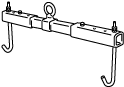
Engine support set
1: 49 UN30 3050
2: 303–050
Engine lifting bracket

1: 49 L017 5A0
2: –
Support hanger
AUTOMATIC TRANSAXLE REMOVAL/INSTALLATION [GW6A-EL]
id0517i21172i1
Special Service Tool (SST)
|
1. : Mazda SST number
2. : Global SST number
|
|||||
|
1: 49 C017 5A0
2: –
Engine support set
|
|
1: 49 UN30 3050
2: 303–050
Engine lifting bracket
|
|
1: 49 L017 5A0
2: –
Support hanger
|
|
Replacement Part
|
washer
Quantity: 1
Location of use: plug
|
Removal
1. Disconnect the negative battery terminal. (See NEGATIVE BATTERY TERMINAL DISCONNECTION/CONNECTION.)
2. Remove the engine cover. (See ENGINE COVER REMOVAL/INSTALLATION [SKYACTIV-D 2.2].)
3. Remove the following parts as a single unit. (See INTAKE-AIR SYSTEM REMOVAL/INSTALLATION [SKYACTIV-D 2.2].)
4. Remove the battery and battery tray. (See BATTERY REMOVAL/INSTALLATION [SKYACTIV-D 2.2].)
5. Remove the front splash shield. (See SPLASH SHIELD REMOVAL/INSTALLATION.)
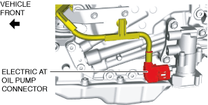
6. Disconnect the electric AT oil pump connector.
ac5wzw00009177
|
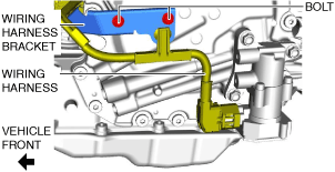
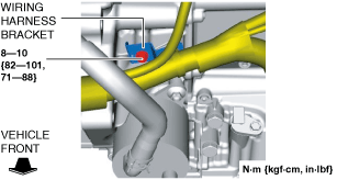
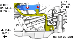
7. Remove the bolts and set the wiring harness and wiring harness bracket in a place which does not interfere with servicing.
ac5wzw00010986
|
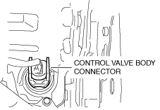
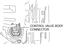
8. Disconnect the control valve body connector.
ac5wzw00009179
|
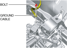
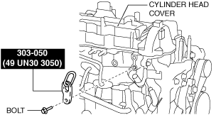
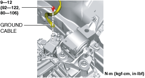
9. Disconnect the ground cable.
ac5wzw00009180
|
10. Disconnect the selector cable from the transaxle. (See SELECTOR LEVER COMPONENT REMOVAL/INSTALLATION.)
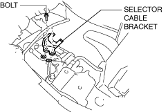
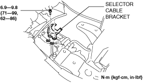
11. Remove the selector cable bracket.
ac5wzw00009182
|
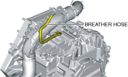
12. Disconnect the breather hose from the transaxle.
ac5wzw00009183
|
13. Remove the joint cover. (See STEERING WHEEL AND COLUMN REMOVAL/INSTALLATION.)
14. Disconnect the intermediate shaft from the steering gear and linkage. (See STEERING WHEEL AND COLUMN REMOVAL/INSTALLATION.)
15. Drain the engine coolant. (See ENGINE COOLANT REPLACEMENT [SKYACTIV-D 2.2].)
16. Remove the EGR cooler. (See EGR COOLER REMOVAL/INSTALLATION [SKYACTIV-D 2.2].)
17. Remove the front tires. (See WHEEL AND TIRE REMOVAL/INSTALLATION.)
18. Remove the front under cover No.2. (See FRONT UNDER COVER No.2 REMOVAL/INSTALLATION.)
19. Remove the front under cover No.1. (See FRONT UNDER COVER No.1 REMOVAL/INSTALLATION.)
20. Drain the ATF. (See AUTOMATIC TRANSAXLE FLUID (ATF) REPLACEMENT [GW6A-EL, GW6AX-EL].)
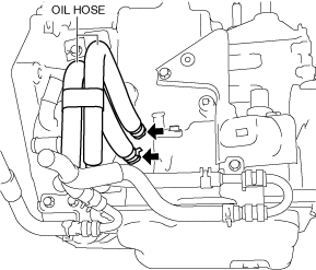
21. Disconnect the oil hoses from the transaxle. (With oil cooler No.2) (See OIL COOLER REMOVAL/INSTALLATION [GW6A-EL, GW6AX-EL (SKYACTIV-D 2.2)].)
ac5wzw00009497
|
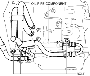
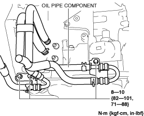
22. Remove the bolts shown in the figure and set the oil pipe component in a place which does not interfere with the servicing. (With oil cooler No.2) (See OIL COOLER REMOVAL/INSTALLATION [GW6A-EL, GW6AX-EL (SKYACTIV-D 2.2)].)
ac5wzw00009498
|
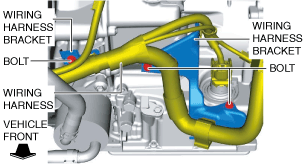
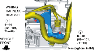
23. Remove the bolts and set the wiring harness and wiring harness bracket in a place which does not interfere with servicing.
ac5wzw00010987
|
24. Disconnect the oil cooler from the transaxle with the hose connected. (Except Automatic Transaxle Replacement) (See OIL COOLER REMOVAL/INSTALLATION [GW6A-EL, GW6AX-EL (SKYACTIV-D 2.2)].)
25. Disconnect the water hose from the oil cooler. (Automatic Transaxle Replacement) (See OIL COOLER REMOVAL/INSTALLATION [GW6A-EL, GW6AX-EL (SKYACTIV-D 2.2)].)
26. Remove the starter. (See STARTER REMOVAL/INSTALLATION [SKYACTIV-D 2.2].)
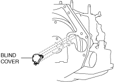
27. Remove the blind cover.
ac5wzw00009187
|
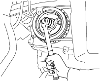
28. Hold the crankshaft pulley to prevent drive plate from rotating.
ac5jjw00003168
|
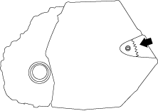
29. Remove the torque converter nuts from the starter installation hole.
ac5jjw00003050
|
30. Disconnect the front ABS wheel-speed sensors from the steering knuckles. (See FRONT ABS WHEEL-SPEED SENSOR REMOVAL/INSTALLATION.)
31. Disconnect the clips securing the brake hose from the front shock absorbers. (See FRONT BRAKE HOSE REMOVAL/INSTALLATION [WITH SINGLE PISTON FLOATING CALIPER].) (See FRONT BRAKE HOSE REMOVAL/INSTALLATION [WITH 2-PISTON FLOATING CALIPER].)
32. Disconnect the tie-rod ends from the steering knuckles. (See STEERING GEAR AND LINKAGE REMOVAL/INSTALLATION.)
33. Disconnect the front lower arms from the steering knuckles. (See FRONT LOWER ARM REMOVAL/INSTALLATION.)
34. Disconnect the front stabilizer control links from the front stabilizer. (See FRONT STABILIZER REMOVAL/INSTALLATION.)
35. Disconnect the front drive shaft (LH) from the transaxle. (See FRONT DRIVE SHAFT REMOVAL/INSTALLATION.)
36. Disconnect the front drive shaft (RH) from the transaxle. (See FRONT DRIVE SHAFT REMOVAL/INSTALLATION.)
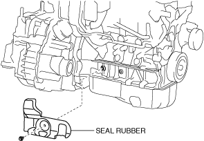
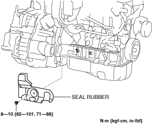
37. Remove the seal rubber.
ac5wzw00004300
|
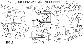
38. Remove the front crossmember component and No.1 engine mount rubber as a single unit. (See FRONT CROSSMEMBER REMOVAL/INSTALLATION.)
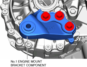
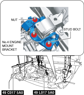
39. Remove the No.1 engine mounting bracket component.
ac5wzw00009188
|
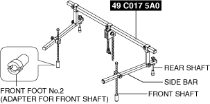
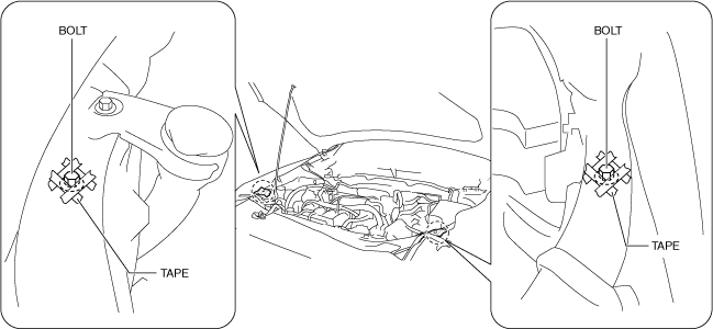
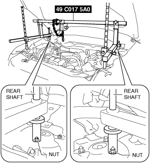
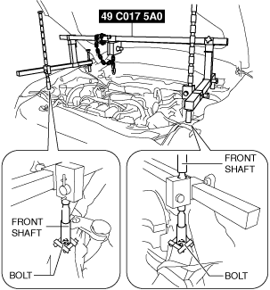
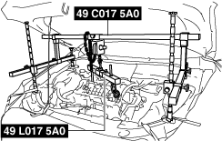
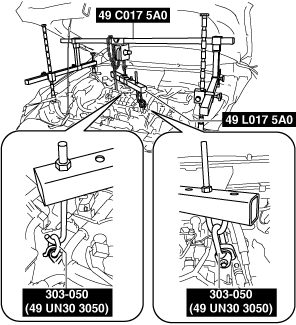
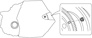
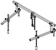
40. Install the SST using the following procedures.
ac5wzw00009189
|
ac5wzw00009190
|
ac5wzw00014478
|
Engine front side
ac5wzw00009192
|
Engine rear side
ac5wzw00009193
|
ac5wzw00009194
|
ac5wzw00012860
|
ac5jjw00010787
|
ac5jjw00010788
|
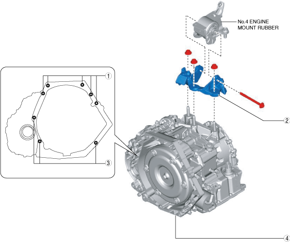
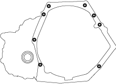
41. Remove in the order shown in the figure.
ac5wzw00009196
|
|
1
|
Transaxle mounting bolts (upper side)
|
|
2
|
No.4 engine mount bracket
|
|
3
|
Transaxle mounting bolts (lower side)
|
|
4
|
Transaxle
|
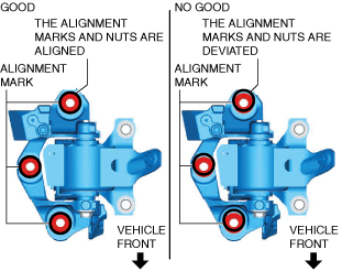
No.4 engine mount bracket removal note
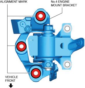
1. Place alignment marks on the locations shown in the figure so that they can be assembled to the same positions as before removal.
ac5wzw00009197
|
2. Remove the No.4 engine mount bracket.
Transaxle mounting bolt removal note
1. Adjust the SST and lean the engine toward the transaxle.
ac5jjw00010787
|
2. Support the transaxle on a jack.
ac5jjw00003179
|
3. Remove the transaxle mounting bolts (lower side).
4. Remove the transaxle.
Installation
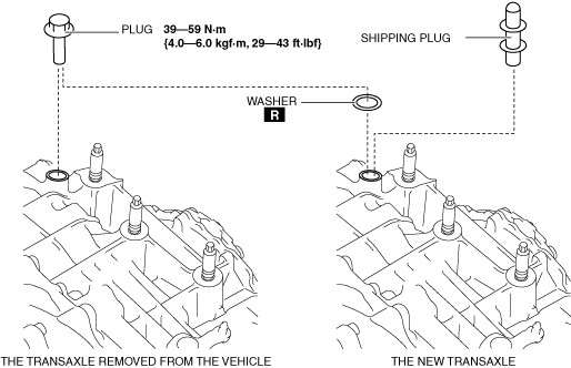
1. If the transaxle is replaced with a new one, perform the following procedure.
ac9uuw00011693
|
2. Verify that the torque converter stud bolts are inserted into the drive plate bolt holes from the starter installation hole.
ac5jjw00003065
|
3. Install the transaxle mounting bolts.
ac5jjw00003066
|
4. Tighten the stud bolts for the transaxle.
ac5wzw00009198
|
5. Install the No.4 engine mount bracket to No.4 engine mount rubber, and temporarily tighten the installation bolt.
ac5wzw00009199
|
6. Lift up the transaxle using the SSTs, pass the transaxle stud bolts through the No.4 engine mount bracket, and temporarily tighten the No.4 engine mount bracket installation nuts.
ac5wzw00009200
|
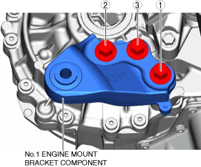
7. Install the No.1 engine mount bracket component, and tighten the installation bolts in the order shown in the figure.
ac5wzw00009201
|
8. Install the front crossmember component and No.1 engine mount rubber as a single unit. (See FRONT CROSSMEMBER REMOVAL/INSTALLATION.)
9. Temporarily tighten the No.1 engine mount rubber installation bolts.
ac5wzw00009202
|
10. Align the positions of the No.4 engine mount bracket installation nuts with the No.4 engine mount bracket.
ac5wzw00009203
|
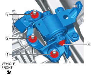
11. Tighten the No.4 engine mount bracket installation nuts and bolt in the order shown in the figure.
ac5wzw00009204
|
|
No. |
Tightening torque |
|---|---|
|
1, 2, 3
|
92—116 N·m {9.4—11 kgf·m, 69—85 ft·lbf}
|
|
4
|
81—99 N·m {8.3—10 kgf·m, 60—73 ft·lbf}
|
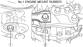
12. Remove the SST (49 C017 5A0).
13. Tighten the No.1 engine mount rubber installation bolts in the order shown in the figure.
ac5wzw00009205
|
|
No. |
Tightening torque |
|---|---|
|
1
|
141—172 N·m {15—17 kgf·m, 104—126 ft·lbf}
|
|
2
|
130—164 N·m {14—16 kgf·m, 96—120 ft·lbf}
|
14. Fix the crankshaft pulley to lock the torque converter against rotation.
ac5jjw00003185
|
15. Tighten the torque converter installation nut.
ac5jjw00003186
|
16. Install the blind cover.
ac5wzw00009206
|
17. Install the starter. (See STARTER REMOVAL/INSTALLATION [SKYACTIV-D 2.2].)
18. Install the seal rubber.
ac5wzw00009622
|
19. Connect the front drive shaft (RH) to the transaxle. (See FRONT DRIVE SHAFT REMOVAL/INSTALLATION.)
20. Connect the front drive shaft (LH) to the transaxle. (See FRONT DRIVE SHAFT REMOVAL/INSTALLATION.)
21. Connect the front stabilizer control links to the front stabilizer. (See FRONT STABILIZER REMOVAL/INSTALLATION.)
22. Connect the front lower arms to the steering knuckles. (See FRONT LOWER ARM REMOVAL/INSTALLATION.)
23. Connect the tie-rod ends to the steering knuckles. (See STEERING GEAR AND LINKAGE REMOVAL/INSTALLATION.)
24. Connect the clips securing the brake hose to the front shock absorbers. (See FRONT BRAKE HOSE REMOVAL/INSTALLATION [WITH SINGLE PISTON FLOATING CALIPER].) (See FRONT BRAKE HOSE REMOVAL/INSTALLATION [WITH 2-PISTON FLOATING CALIPER].)
25. Connect the front ABS wheel-speed sensors to the steering knuckles. (See FRONT ABS WHEEL-SPEED SENSOR REMOVAL/INSTALLATION.)
26. Connect the water hose to the oil cooler. (Automatic Transaxle Replacement) (See OIL COOLER REMOVAL/INSTALLATION [GW6A-EL, GW6AX-EL (SKYACTIV-D 2.2)].)
27. Connect the oil cooler to the transaxle with the hose connected. (Except Automatic Transaxle Replacement) (See OIL COOLER REMOVAL/INSTALLATION [GW6A-EL, GW6AX-EL (SKYACTIV-D 2.2)].)
28. Install the wiring harness bracket.
ac5wzw00010988
|
29. Tighten the wiring harness bracket installation bolts in the order shown in the figure.
ac5wzw00010989
|
30. Install the oil pipe component. (With oil cooler No.2) (See OIL COOLER REMOVAL/INSTALLATION [GW6A-EL, GW6AX-EL (SKYACTIV-D 2.2)].)
ac5wzw00009499
|
31. Connect the oil hose to the transaxle. (With oil cooler No.2) (See OIL COOLER REMOVAL/INSTALLATION [GW6A-EL, GW6AX-EL (SKYACTIV-D 2.2)].)
ac5wzw00009500
|
32. Install the front under cover No.1. (See FRONT UNDER COVER No.1 REMOVAL/INSTALLATION.)
33. Install the front under cover No.2. (See FRONT UNDER COVER No.2 REMOVAL/INSTALLATION.)
34. Install the front tires. (See WHEEL AND TIRE REMOVAL/INSTALLATION.)
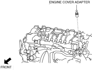
35. Install the engine cover adapter.
ac5wzw00014479
|
36. Install the EGR cooler. (See EGR COOLER REMOVAL/INSTALLATION [SKYACTIV-D 2.2].)
37. Connect the intermediate shaft to the steering gear and linkage. (See STEERING WHEEL AND COLUMN REMOVAL/INSTALLATION.)
38. Install the joint cover. (See STEERING WHEEL AND COLUMN REMOVAL/INSTALLATION.)
39. Connect the breather hose to the transaxle.
ac5wzw00009183
|
40. Install the selector cable bracket.
ac5wzw00011787
|
41. Connect the selector cable to the transaxle. (See SELECTOR LEVER COMPONENT REMOVAL/INSTALLATION.)
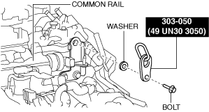
42. Connect the ground cable to the No.4 engine mount bracket.
ac5wzw00009210
|
43. Connect the control valve body connector.
ac5wzw00009212
|
44. Install the wiring harness bracket.
ac5wzw00010990
|
45. Connect the electric AT oil pump connector.
ac5wzw00009177
|
46. Install the front splash shield. (See SPLASH SHIELD REMOVAL/INSTALLATION.)
47. Install the battery and battery tray. (See BATTERY REMOVAL/INSTALLATION [SKYACTIV-D 2.2].)
48. Install the following parts as a single unit. (See INTAKE-AIR SYSTEM REMOVAL/INSTALLATION [SKYACTIV-D 2.2].)
49. Connect the negative battery terminal. (See NEGATIVE BATTERY TERMINAL DISCONNECTION/CONNECTION.)
50. Refill the engine coolant. (See ENGINE COOLANT REPLACEMENT [SKYACTIV-D 2.2].)
51. Add the ATF. (See AUTOMATIC TRANSAXLE FLUID (ATF) REPLACEMENT [GW6A-EL, GW6AX-EL].)
52. Install the engine cover. (See ENGINE COVER REMOVAL/INSTALLATION [SKYACTIV-D 2.2].)
53. Perform the “TCM configuration” (Automatic transaxle replacement). (See TCM CONFIGURATION [GW6A-EL, GW6AX-EL])
54. Perform the “Initial Learning” (automatic transaxle replacement). (See INITIAL LEARNING [GW6A-EL, GW6AX-EL].)
55. Perform the “Mechanical System Test”. (See MECHANICAL SYSTEM TEST [GW6A-EL, GW6AX-EL].)